Moving on...............
VDI,
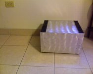
Very nice looking case, I like the "engine turning". look, very custom! What materials did you use to accomplish the look? Was the aluminum a mirror finish prior to turning?
Are those the Conrad MF35-151.5 heatsinks? What are the dimensions? Any internal photos?
Thanks,
Ron
VDI,
Very nice looking case, I like the "engine turning". look, very custom! What materials did you use to accomplish the look? Was the aluminum a mirror finish prior to turning?
Are those the Conrad MF35-151.5 heatsinks? What are the dimensions? Any internal photos?
Thanks,
Ron
Case is 3/8 alum plate. Mirror finish orginally, but scratches easily. It's rather soft, forget the number right now. Easy to cut, but not fun to tap. It smears when running a tapping tool thru holes. I did a real bad job of lining up holes. Never get them just right!
A friend helped drill holes in rear plate and bottom he and ran the pattern on the outside with a rotary sander. Not the prettiest, but looks like it's been in a battle! Heat sinks are from Apex Jr. They are gold. Spray painted with charcol grill paint that can withstand 1200 F.
Need to redo sinks because I didn't prep the material correctly the first time, but the color is super cool. Sinks look like an angry storm cloud...if you like that sort of thing. 🙄
It's about 9"h x 12"d x 16"w. Will post a couple more pics of inside tomorrow.
Hi Renron,
UL and BS/EN standards appears on a cursory glance to be different.
UL does say several seconds.
BS/EN states <=200ms @ 5times Idelta n
<=40ms @ 1times Idelta n
If I have read these correctly then there is a fundamental difference in trip timings when the imbalance between flow and return is ~= Idelta n.
BS also states that trip will occur when imbalance is between 0.5 times Idelta n and 1 times I delta n.
But I did not see a reference to timing for the lower range of leakage current.
AndrewT said:Hi Renron,
UL and BS/EN standards appears on a cursory glance to be different.
As expected as our typical household voltages differ
UL does say several seconds.
As I had stated in an earlier post
BS/EN states <=200ms @ 5times Idelta n
<=40ms @ 1times Idelta n
The standards for BS/EN differ from those in the USA. BS/EN have different ratings of their devices by mA values. Some are as small as 10mA IAn which are used in school laboratory benches. Yes, trip timings vary depending on their mA designations, some even have delayed trip timers. Cool
If I have read these correctly then there is a fundamental difference in trip timings when the imbalance between flow and return is ~= Idelta n.
Correct, that's what I understood as well.
BS also states that trip will occur when imbalance is between 0.5 times Idelta n and 1 times I delta n.
"With a leakage current equal to 50% of
the rated residual operating current (IΔn ) applied, the
RCD should not operate"
But I did not see a reference to timing for the lower range of leakage current.
I have attached at table from the 16th edition requirements for testing RCDs. In the latter 17th edition I could not find the timing table they referred to, but they did stated that the table had not changed. There are other specifications which relate to the maximum earth fault loop impedance for the relative value in mA of the RCD.
This is much deeper than I ever expected to delve into this topic.
I find it fascinating and informative! Brilliant!
Great info here:
2008 Requirements for testing RCDs
Ron
Attachments

we in the UK have yet another rule for an RCD/RCCB/RCBO protected circuit.
The total standing earth leakage currents for all appliances on a circuit must be less than 25% of the trip rating.
A 30mA trip requires the earth leakage to be <=7.5mA.
This in turn demands that the Y capacitors (Line to Earth/PE) be small to conduct the minimum current to Earth.
The total standing earth leakage currents for all appliances on a circuit must be less than 25% of the trip rating.
A 30mA trip requires the earth leakage to be <=7.5mA.
This in turn demands that the Y capacitors (Line to Earth/PE) be small to conduct the minimum current to Earth.
Andrew
Having built my F5 boards I am about to put everything into their boxes, so I have been trying to catch up on this thread. I think I have read everything about the CL6 devices and how they are used on 120Vac transformers and on 230Vac transformers but only where each of them is using twin 0-120v primaries.
I have two 225va 18-0-18 transformers which have a single 0-230 primary; trying to interpret the 120Vac version there is a Thermistor on the 120v supply on one primary and one Thermistor on the 0v supply on the other primary.
The only circuit I have been able to find is this: -http://www.semitec.co.jp/english/products/pdf/Power_Thermistor.pdf. This shows the thermistors being used after the rectifier.
So - do I put one CL6 on the 230v AC and one on the Ov?
no,
you can try putting just one CL60 in the primary feed, but I think the resistance is too low for effective current reduction on 240Vac supplies.
I would recommend using two CL60 in series in the primary feed. That will reduce the peak current by about a further 30%.
The location of the CL60 is a choice you must make.
The device is connected to the mains lines and must be considered as potentially lethal.
I think there is an argument for locating the Thermistor in the (UK) Neutral Line where it will have near zero volts on it.
Others argue that it must be in the Live Line.
It's arguable which is safer. Certainly putting one each in both the Live and Neutral cannot be safer than the other options.
But you must protect from inadvertent touching even with the box opened up for inspection/maintenance.
Thank you all for the replies - since I have a bunch of CL6's I will initially try two of them in series on the Neutral feed.
Would it be better (in general terms) to go for twin primaries with the suggested series CL6's between the windings rather a single primary with the sereis CL6's on the neutral line?
I ask as I am about to order some more transformers for the F2.
Alan
Would it be better (in general terms) to go for twin primaries with the suggested series CL6's between the windings rather a single primary with the sereis CL6's on the neutral line?
I ask as I am about to order some more transformers for the F2.
Alan
no,
use a single primary where you only have access to a single supply voltage.
Twin primaries increases the cost and possibly the field leakage.
Keep in mind that most transformers are available as 230:Vsecondary, but your supply varies between 216Vac and 254Vac.
You have typed CL6 again.
What is a CL6?
AndrewT said:no,
use a single primary where you only have access to a single supply voltage.
Twin primaries increases the cost and possibly the field leakage.
Keep in mind that most transformers are available as 230:Vsecondary, but your supply varies between 216Vac and 254Vac.
You have typed CL6 again.
What is a CL6?
Silly me - should be CL60.

On the mains side I wish people in this country would make the transformers for 240v - at least it would keep the transformer outputs closer to the required values. I usually find that the mains is higher than 240v - cannot say that I have seen very low readings. Either that or have lower secondaries and hope the mains voltage is high.
Thanks for the primary info.
Alan
Bridge Rectifiers
Is using a bridge rectifier with 50v PIV and 25 amps too small for the F5? The recommended F4 PS schem says 35A 200V.
If we are looking at 18v off the transfo taps, is 50V a safe enough margin?
Thanks,
Vince
Is using a bridge rectifier with 50v PIV and 25 amps too small for the F5? The recommended F4 PS schem says 35A 200V.
If we are looking at 18v off the transfo taps, is 50V a safe enough margin?
Thanks,
Vince
Re: Bridge Rectifiers
Since the peak inverse voltage is rated at 50V, maximum RMS bridge input voltage is to be no more than 35V(rms). So, I think the bridge questioned is considered acceptable with the 18V(rms) input.
🙂
vdi_nenna said:
Is using a bridge rectifier with 50v PIV and 25 amps too small for the F5? The recommended F4 PS schem says 35A 200V.
If we are looking at 18v off the transfo taps, is 50V a safe enough margin?
Since the peak inverse voltage is rated at 50V, maximum RMS bridge input voltage is to be no more than 35V(rms). So, I think the bridge questioned is considered acceptable with the 18V(rms) input.
🙂
18+18Vac will develop <=60Vdc across the rectifier in worst case conditions.
Using a 50V rectifier is risky, just as using 25V capacitors is risky.
Using a 50V rectifier is risky, just as using 25V capacitors is risky.
If the bridge blows, caps may see reverse voltage and may explode in the worst case. Wether your speakers will be happy with the fed funny signal is also hard to say.
If only half the bridge blows (and goes open), you get most likely nice DC at the output.
Believe me, you don't want a blown bridge.
Go for a larger voltage rating.
Have fun, Hannes
EDIT: only blown Schottky bridges are more fun, they usually short.
If only half the bridge blows (and goes open), you get most likely nice DC at the output.
Believe me, you don't want a blown bridge.
Go for a larger voltage rating.
Have fun, Hannes
EDIT: only blown Schottky bridges are more fun, they usually short.
Just a shot in the dark, but I calculated 18+18=36 * 1.414= 50.904v peak.
or 24*=48 * 1.414 = 67.87v peak?
or 24*=48 * 1.414 = 67.87v peak?
- Home
- Amplifiers
- Pass Labs
- F5 power amplifier