tinitus said:Well, in that case
I understand that a load into half the impedance means only half the voltage is needed
But is that also equal to whats available
Im really trying to understand your point, but dont
This is really not my strong side, and has nothing to do with "not reading"
But I have always thought that current would rise in low impedance load
I must apologize, I didn't read your entire post before I answered.
The greater load will demand more current but it is not available if the bias current is optimized for a lesser load such as 8ohms, as the F5 is.
Best, Bill
Ahhh, thanks
"Possible with good hardware"
Ehhh, maybe I do have the heatsinks, but thought they were a bit too much
But apparently just right
I bought it long ago as 1meter, and cut it in two
Unfortunately I got the idea that 400mm was enough to do 150watt AB/8ohm, and cut off 100mm
So now its 300mmx400mmxx40mm, base 10mm
A small light i entering my head, just dimmed still
Still not 100% sure
Raise bias to 2.5A?
How about using 2x 15Vac trafos? nah, probably not too smart move
I wonder, is there an upper limit to bias due to curcuit
Or is it only heat related
With this higher bias, what happens when load changes
This probably says "still dont get it"
But Im really trying
Im sure others feel like me now
But I know, you cannot explain it better now
Need to digest
Not sure about heatsinks either
Fisher have a 300mm
Seems their best one reaches 0.2 K/W cooling at about 200mm length?
Dont know? but curve looks like it goes even lower with increased length
Available at 100/150/200mm and 1meter(to cut at will)
bobodioulasso said:Hi Tinitus
Staying in class A: two times the bias current in the load is the limit.
12.5w into 16 ohms / bias 0.625A
25w into 8 ohms / bias 1.25A
50w into 4 ohms / bias 2.5A
At 1.25 bias and 4 ohms load we leave class A at 12.5w
when load current reaches 2times the bias current
P peak = 2Prms.
The only formula is P=RxI^2
Is that clear for you?
Attachments
Hi Tinitus.
Class a amp works like this:
When idle the two halves run equal current: the bias.
Each half runs its current through the load but as they are equal and in opposite direction the load see no current.
When a signal is applied, current varies the same quantity into the two halves but opposite .One side increase while the other decrease.
This variation's amplitude is from bias value to twice this value.
When one side is 2xbias, the other side is zero.
This explains why one leaves class A at 2xbias.
The upper limit is the is due to the output devices limits.
Class a amp works like this:
When idle the two halves run equal current: the bias.
Each half runs its current through the load but as they are equal and in opposite direction the load see no current.
When a signal is applied, current varies the same quantity into the two halves but opposite .One side increase while the other decrease.
This variation's amplitude is from bias value to twice this value.
When one side is 2xbias, the other side is zero.
This explains why one leaves class A at 2xbias.
I wonder, is there an upper limit to bias due to curcuit
The upper limit is the is due to the output devices limits.
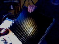
Hmm, i picked up this old case awhile ago used. (It appears to be a par-metal case.) The dimensions on it are 16"w x 12"d x 6"h.
I've got a clam shell for it, I was wondering if this maybe a good fit for the F5. (I mean all the components fit, but I'm unsure of finding the right heatsinks, and adapting it to this would be an issue?
I'm kind of stalled at the moment, waiting on a group buy.
Anyways, here's what it looks like...
http://picasaweb.google.com/merlin2049er/PassLabsF5?feat=directlink
merlin2069er said:Hmm, i picked up this old case awhile ago used. (It appears to be a par-metal case.) The dimensions on it are 16"w x 12"d x 6"h.
I've got a clam shell for it, I was wondering if this maybe a good fit for the F5. (I mean all the components fit, but I'm unsure of finding the right heatsinks, and adapting it to this would be an issue?
I'm kind of stalled at the moment, waiting on a group buy.
Anyways, here's what it looks like...
http://picasaweb.google.com/merlin2049er/PassLabsF5?feat=directlink
On my designs I use internal heatsinks with a pair of fans, one fan sucks in air and the other blows it out at the opposite corner.
This has worked reliably for me with my disco and guitar amps.
The disco amp gets some serious stick and is in and out of gigs often.
R-K Rønningstad said:That was pretty well put indeed!
Indeed yes
I was closing in on that, and it confirms it in detail why
I did wonder whether the "leaving classA" at twice the bias current, actually was due to the two output trannies sharing the load
Man, my logic mind just love that 🙂
Calculations, well you know now

Never thought about classA having these issues
Bias rules 😀
Thanks
Hi Tinitus
I will cut to the chase here.
If you have 4Ohm speakers like me and you want 25W (CLASS A) into 4Ohms, then you need to increase the bias to 1.8A.
Is that clear enough?
If you want more than this you will need to parrallel the output mosfets.
Anyway tell me what you want to achieve and I will do the calculations for you, or if you want I can attach a spread sheet which will allow you to do the calculations.
This applies to a push pull design.
If it was single ended you would need 3.6A.
thanh1973 said:Hi Tinitus
If you have 4Ohm speakers like me and you want 25W (CLASS A) into 4Ohms, then you need to increase the bias to 1.8A.
Is that clear enough?
If you want more than this you will need to parrallel the output mosfets.
Heavens no, 25watt is perfectly fine, as long as it stays that
25watt is all I wanted
Next step is to try and determine what trafo voltage I get with my actual mains voltage
Anyway, Thanks fore the kind offer
And thanks to all for the patience
hi guys
im interested in this also (parralell output devices)
how is this done id like 50w class a into 2 ohm if possible
i have 8 spare output devices if needed
do i have to change anything else in the circuit to suit
regards sheafer
im interested in this also (parralell output devices)
how is this done id like 50w class a into 2 ohm if possible
i have 8 spare output devices if needed
do i have to change anything else in the circuit to suit
regards sheafer
bobodioulasso said:...
Staying in class A:
P peak = 2Prms.
P=RxI^2
12.5w into 16 ohms / bias 0.625A
25w into 8 ohms / bias 1.25A
50w into 4 ohms / bias 2.5A
If
P=RxI^2
Then
I = sqrt(P/R)
Plugging in the 50W example:
I= 3.5355... or 2.5*sqrt(2)
Maybe you could also explain why this is different by a factor of sqrt(2) than your calculation example.
It would also be nice to provide a formula for the required supply rails for a Class A amp for given max power and load impedance. Then we'd be all set. What voltage drop across the output transistors would be reasonable?
Still small issues to clear, it seems
How about doing a simple "table" with some of the options 😉
Ehhh, time to save some all this in my F5 file 🙂
How about doing a simple "table" with some of the options 😉
Ehhh, time to save some all this in my F5 file 🙂
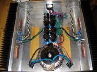
Here is a simplified version of the circuit, with the output stage paralleled 3 times.
To get 50W Class A into 2Ohms you need Bias current of about 3.6A.
Which would be 1.2 A each (3.6/3 = 1.2).
If you have two in parallel then you will have 1.8 A through each (3.6/2 = 1.8)
You take these measurements across the source resistors (0.47 Ohm Resistors).
To get 1.2A each - you need to measure 564mV across the source resistors.
To get 1.8A each (for 2 x parallel output stage) you need to measure 846mV across the source resistors.
Attachments
thankyou thanh
great so it seems doable
to do this do i just run flying leeds from the legs on one output device to the other
regards sheafer
great so it seems doable
to do this do i just run flying leeds from the legs on one output device to the other
regards sheafer
run a fly lead before the gate resistor, and run a fly lead from the power rails, and then run a fly leed from the drain of the new mosfet to the output.
You need a an extra gate resistor (47Ohm) for each mosfet.
You also need an extra Source resistor for each mosfet (0.47Ohm).
I hope you can picture this in your mind. Please refer back to the schematic I attached to avoid any misunderstanding.
You could attach the extra source and gate resistors directly to the pins of the mosfet.
Also try and keep the fly leeds as short as possible.
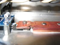
my copper wings
With the extra bias comes extra heat and dissipation. I had an idea to pull heat off of the top of mosfet on to a copper heat spreader/clamp. I do not yet have a meter with a temperature probe, but I may buy one just to measure the difference of the mosfet with and with out the clamp.
I can say I think it works well. Without the clamp, my heatsinks had a hot spot between the two mosfet until the amp really warmed. When touching the fet without the clamp I could only hold my finger against them for a second or two and the sinks seemed much cooler.
With the clamp, the heatsinks warm more evenly and I can barely feel the difference between the IC and the sink.
The copper junction surfaces are polished with 600 grits sand paper and honing oil. I used grease at the junctions.
Oh, when I say no clamp I did use a screw and washer
Here's a few pictures
Attachments

Great Idea.
If you could do the same thing with fins on the copper, this would improve things again.
Another idea would be to place a peltier device between the copper and mosfet (hot side attached to copper and cold side attached to mosfet).
I have been playing with these peltier devices at work and they get bloody cold (easily below zero degrees celsius) the only thing is you need to cool the hot side to get the most out of them as the heat generated on the hot side limits its cooling performance on the cold side.
I am not suggesting anyone seriously consider this idea unless they really like fiddling around. For starters you will need an extra souce of power to run the peltier (you could use a switch mode power supply I suppose).
I just thought this might help someone out with a future project.
- Home
- Amplifiers
- Pass Labs
- F5 power amplifier