sandbasser said:I'm very much a newbie here... but I decided to join the fun and build an F5. I've ordered boards and I'm acquiring parts now...
I've been closely examining the doc provided in the 'F5-om_sm-080527.pdf' file. On the last page there's a schematic for a Power Supply. My question is I don't understand the function of the thermistor in the lower right hand side of the schematic... (it apparently connects 'output' ground with chassis ground) I'm not too sure of what to use and where to mount it... I thought thermistor had to be near some source of heat to protect. So, what is the thermistor for; and where should it be mounted???
Any assistance would be appreciated.
Thanks,
I think the thermistor was to help prevent a ground loop.
f5 not blowing fuses but....
well more fun-
got the mosfets swapped around and no fuse blowing - yeeeeeeeeeeeehaaaa- shoulda stopped there for the pm but NOOO-
Now
I can't seem to get the bias set across P1 & P2 so that i don't see serious dc voltage on the speaker binding posts-= we are talking 20- 24volts here- I have two multimeters reading dc across P1 & P2 and at certain points they track nicely- but I can't drive the dc at the binding down- I've spent much time turning those leetdle brass screws back and forth and back and forth( such a headache I've got)
so have no idea where they are vis a vis ohmage(I'm sure that ohms law and some smart guy out there could tell me how to figurere that out) but the high volts on the binds post as me a tad scared- is this normal till you hit the magic balance or is there
something sinister going on around here?
inquiring minds wanna know
rob
thanks for the "that a boy" NP
Hi Rob,
nice to see someone building stuff !
have you checked if the output stage mosfets are still operational ?
or re-checked after you put them back in ?
i have blown a few of IRFP240/9240 on the test bench and sometimes you can get low resistance from gate to drain or drain to source which is easy to check for.
this is probably the last thing you want to hear right now but if you simply de-solder the mosfet and do a basic DMM check of the mosfet
make sure its not low ohms between pins this can save you alot of additional headaches.
OR with the amp on (carefully dont slip and short the pins together)
make sure the mosfet is not acting like a switch, if it is it will have a very low voltage drop across drain and source pins.
(yes i know this is a "rough as guts" method)
if any one disagrees or wants to chime in and add a better method here feel free to hammer burn abuse argue disagree in general etc.
Hope you get it going looks like another nice design by Nelson Pass....
I have a about 80 IRFP240/9240 left over i might have to try it out !
Incidentally Nelson, if you have some spare XA200.5 i can lift them all the way to my house. (bad joke)
-Dan
sandbasser said:. . . thermistor . . . where should it be mounted???
Here, for example. >🙂<
Attachments
@ rob :
www.passdiy.com/pdf/matching.pdf
read ;
desolder mosfets , test them looking at procedure in first pic
www.passdiy.com/pdf/matching.pdf
read ;
desolder mosfets , test them looking at procedure in first pic
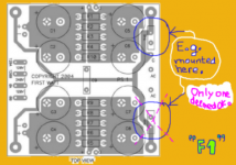
roblenk: Are you sure you have the output resistors in the right holes on the PD boards? I had mine in wrong and had exactly the problem you are having.
See the 4 orange 100R resistors in the pic below:
Well the leg nearest you in this pic is actually in the wrong hole - it should be in the next hole back. If you actually look at the board you will see where I mean.
Also - on using the smaller mica insulator - just check for continuity when cold and then when hot. What happened on mine was that the source resistors went open circuit.
Mosfets are probably alright - they're pretty hardy. Just measure the voltages across the legs and check against the manual and you will know if they are ok. Most likely they are.
If thats your problem and when you fix it, the biasing becomes easy, just be sure you turn the pots down all the way (ie 0R). You'll get no bias voltage for a few turns and then it start slow and then faster. Allow it to settle in between changes.
Report back and let us know how you get on....
*************************
Sandbasser:
The thermistor is there to help prevent ground loops by putting some resistance between circuit ground and safety earth. The idea is that there is higher resistance when no current is flowing to earth (ie the way it should be) but then if something should happen to cause the current to flow (ie short from circuit to chassis) then the thermistor quickly warms up, the resistance drops and the fuse blows/breaker trips.
Another way is to wire in a 5 or 7W 10-20R resistor in parallel with a 0.1nF cap and 2 diodes wired back to back. All components rated highly enough to stand the current and voltages involved (works well but not the officicl "pass" way of doing it). The thermistor works great.
Fran
See the 4 orange 100R resistors in the pic below:
An externally hosted image should be here but it was not working when we last tested it.
Well the leg nearest you in this pic is actually in the wrong hole - it should be in the next hole back. If you actually look at the board you will see where I mean.
Also - on using the smaller mica insulator - just check for continuity when cold and then when hot. What happened on mine was that the source resistors went open circuit.
Mosfets are probably alright - they're pretty hardy. Just measure the voltages across the legs and check against the manual and you will know if they are ok. Most likely they are.
If thats your problem and when you fix it, the biasing becomes easy, just be sure you turn the pots down all the way (ie 0R). You'll get no bias voltage for a few turns and then it start slow and then faster. Allow it to settle in between changes.
Report back and let us know how you get on....
*************************
Sandbasser:
The thermistor is there to help prevent ground loops by putting some resistance between circuit ground and safety earth. The idea is that there is higher resistance when no current is flowing to earth (ie the way it should be) but then if something should happen to cause the current to flow (ie short from circuit to chassis) then the thermistor quickly warms up, the resistance drops and the fuse blows/breaker trips.
Another way is to wire in a 5 or 7W 10-20R resistor in parallel with a 0.1nF cap and 2 diodes wired back to back. All components rated highly enough to stand the current and voltages involved (works well but not the officicl "pass" way of doing it). The thermistor works great.
Fran
Re: f5 not blowing fuses but....
If sure that all FET pins are correctly connected and Q3/Q4 are
electrically well insulated from the heatsink, I would try this too.
Good Luck . . . >🙂<
rob lenk said:. . .
If sure that all FET pins are correctly connected and Q3/Q4 are
electrically well insulated from the heatsink, I would try this too.
Good Luck . . . >🙂<
Attachments
woodturner-fran said:roblenk: Are you sure you have the output resistors in the right holes on the PD boards? I had mine in wrong and had exactly the problem you are having.
Yup, if it's like in a pic here: http://www.diyaudio.com/forums/attachment.php?s=&postid=1794642&stamp=1238967849 then it's in the wrong holes.
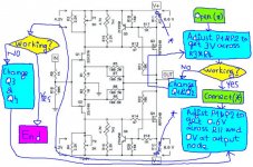
BABO ..... you're my .....
BASIC Master ........

Babowana said:
........
Good Luck . . . >🙂<
BASIC Master ........
Re: BABO ..... you're my .....
That's the best decision tree I've seen in a while!
Babowana said:
If sure that all FET pins are correctly connected and Q3/Q4 are
electrically well insulated from the heatsink, I would try this too.
Good Luck . . . >🙂<
Zen Mod said:
BASIC Master ........
That's the best decision tree I've seen in a while!
f5- output resistor locations
Fran and Peter
if I read your posts correctly then of the three holes for the output resistors the pad that is actually in the rectangle is not used? The corret ones are by output/ v+/ and v- and by the transistors?
Please confirm and I'll be spending my evening tomorrow pulling the boards yet again- such fun!
Just imagine, like child birth all we'll remember when all said and done is how good the music sounds and that "I built it myself-kind of"
as always thanks for the help fellows
rob
f5 yep yep my bad
fran/peter
as I look at one of your pictures Peter I see the resistor placement clearly(how do you take such nice pics?)
Fran thanks for your experience and glad to see I'm not the only one "putt'em in the wrong hole".Que sera!Was everything ok after you changed the resistors or did you have to replace the mosfets?
Zen Mod- thanks for the reference to the Pass info on measuring mosfets
Sincerely, thanks for all your input.
Here's to a better tomorrow
cheers
rob
Peter thanks for the link for the aluminum pads- is that all there is ,no mica underneath?
The aluminum oxide pads replace mica, you also need thermal paste with them.
Regarding resistors, regular 3W or 5W types install as in picture here: http://www.audiostereo.pl/zalaczniki/1261939_1.jpg the additional pads in a center are for small MK132 or resistors in TO-220 package size and install like this: http://www.audiostereo.pl/zalaczniki/1272620_1.jpg
How I make those pics: good light and good lens 😉
f5 an ongoing story
thanks peter
good light and good lens.....I guess that counts my .3 megapixal in my dark dank basement out.
que sera
r
thanks peter
good light and good lens.....I guess that counts my .3 megapixal in my dark dank basement out.
que sera
r
Mosfets were fine, no damage at all. I also installed one of the jfets backwards as well during this build and it was fine too.
Fran
Fran
kaput
Ello all
Trying to finish off my F5 here , thought I had it licked! no chance. Last things I did was do the earth connections and mains stuff for my two channels. Im using cvilliers boards. As an overview I have two channels but Im trying to sort one that powers up and sits at 0.00 dc on output and 0.6v across r11/12. If I connect an input with some audio the dc on the output goes up to 16v or so . No audio is outputed either... I initially checked my wiring and noted that the output mosfets short from signal to drain when powered up. And for a few seconds when not powered up. They are fully insulated from the chassis unless the chassis earth is connected.
Any ideas? befor I start desoldering and replacing bits.
cheers
dave
Did you check that your source is dc free?If I connect an input with some audio the dc on the output goes up to 16v or so
dhole said:no dc on source... but cheers
Have you tried to measure DC on the output with both shorted and open inputs?
- Home
- Amplifiers
- Pass Labs
- F5 power amplifier