@ rob :
try with multimeter have you contact between mosfets and heatsink ....NEVER try mosfets without heatsink , if they're intended to be mounted on them .
did you set both trimpots to zero ?
check that with multimeter ; that way you'll have 0 Volts between G and S of output mosfets and they will be closed ie. not conducting ....
off course - triple check every part - mounting , value , position .....
few boyz already swapped either input jfet's position , or output mosfets .....
woodturner-fran said:lgreen: all sounds ok, except you should be seeing 0.568V approx across R11 and R12 - maybe a typo? Maybe watch the temp when you have it cased. That will add another bit to the temp.
rob lenk: Both your pots turned down all the way? Have you tried hooking up just one board to see what happens? IIRC, the F5 needs a 3A slow blow fuse for 120VAC operation?
Fran
Yes it is that voltage across R11 and also across R12. The sink "extremities" are no hotter than 57 C but when I probe the MOSFET directly by touching the temp probe to the junction of the MOSFET and the washer/screw that pushes it to the heatsink, that is 71C. Will it live?
This is without fan, but fan is coming later...
Rob Lenk- with the pots turned down to zero you should draw little or no current into R11 and R12. Only when you turn them up quite a bit do you start to draw power into your amp boards. You may have hooked up the MOSFETS backwards (one parts list had them swapped) or crossed some wires. Are you measuring the voltage across R11 and R12, what do you see?
I turned mine up to 120VAC with a variac no problem with a 1A fast fuse, 1 channel; using 5A fast now cause I got nothing ese.
lgreen: I'd say you should be ok - but probably at the outside edge of where you want to be. It would be wise to think of the temp in terms of the rise above ambient. So what temp will your room get to in summer. If you are measuring that 57 degC outside in a cooler workshop, then be prepared for it to rise another bit inside. Also, what temp the inside of the case gets to?
The whole lot kinda works together. My mini-A got to 55-60degC and it sounded pretty good for it - but in the end I went back and added some fans. Did you see the little pass circuit for fan control? Very nifty, gives a full shot of power to get the fan running and allows you to run the fan at voltage where it mighten start otherwise.
Fran
is 57degC at the corner of the backplate or right out at the tip of the fin?lgreen said:The sink "extremities" are no hotter than 57 C but when I probe the MOSFET directly by touching the temp probe to the junction of the MOSFET and the washer/screw that pushes it to the heatsink, that is 71C.
What is the thickness of that 8in * 5in backplate?
It looks too thin. That would explain why the transistor bolts are running @ 14Cdegrees above the main sink temp.
f5 problems
checked my setup with Peter daniel's pics on-line who is also using the irf 240/9240 and the orientation of the mosfets appears correct-
i know i've turned one boards pots all the way to 0 ohms(for both pots) and i think i left the other at 50 ohms(ditto) just cann't leave well enough alone i guess-this is the proper starting point for the bias adjustment-yes-issues?
mmmmm........
I poked around with my multimeter tonight and was able to find continuity between the heat sink,the mosfet and the center bolt with which i attached the mosfet-it puzzles me though since the plastic body of the mosfet is isolated from the ground plane "across its back" and the hole that the bolt goes through has a pretty wide isolation ring or"hip"-do I need to further isolate the bolt from the heatsink/mosfet- i have used mica between the mosfet "back" and the heat sink with grease between both junctions-If I use a plastic flanged thru hole I would think it would melt- thoughts and suggestions?
thank you
rob
Re: f5 problems
bolt isn't your culprit ;
look for any metal bit between mosfet and heatsink ...
desolder mosfets from pcb , if needed ; that way you'll be sure what you are measuring
rob lenk said:checked .....
bolt isn't your culprit ;
look for any metal bit between mosfet and heatsink ...
desolder mosfets from pcb , if needed ; that way you'll be sure what you are measuring
Yes, a little bit of grit will do it. Something else to watch out for: If you are using the mica spacers meant for TO-3 transistors (the keystone ones posted back aways) note that they have extra holes - if you orient them the wrong way around one of the holes is under the mosfet and you will get a short. Also make sure your heatsink surface is flat around the tapped hole etc.
Take off your boards, clean the mosfets and spacers with some alcohol, do the same for the heatsink. Then use some fresh heatsink grease and affix again. Check for continuity. When the mosfets are hot check again - I lost some of the source resistors cos of some grit/metal swarf that only shorted when the heatsinks got hot.
Clean it all down and put it back together again - I'd be very hopeful it will be AOK then.
Fran
f5 problems
great advise guys- many thanks for your thoughts
looks like tomorrow I'l be grinding and cleaning, and cleaning, and cleaning and regreasing!!
Peter given the above advise would you advise against silver impregnated grease vs straight heat grease- believe it or not my local radio shack has three different grease coupounds- no mica but three compunds!-
I am using the t-03 mica.Wwould I be better off trimming the holes off and putting two together?
inquiring minds....
again many thanks for your input-s
rob
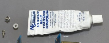
I'm using regular thermal paste, nothing fancy. OTOH, I don't use mica but aluminum oxide pads and never had problem with those: http://ca.mouser.com/Search/ProductDetail.aspx?qs=2v7q0MSBcBMwt5GBytMENg==
Attachments
Kapton Tape
Another good solution is Kapton tape. Small Parts has it in stock. See http://www.smallparts.com/CS-Hyde-P..._s=center-3&pf_rd_m=AIUBT5HP6PMAF&pf_rd_t=301
This is 3 mil self-adhesive (silcone) insulating tape which comes in a 30' x 1/2" roll for ~ $ 3.00, (although they are currently out of stock at this length.) This stuff is good to 500 degrees F, has lower thermal resistance than mica, Berquist Silpads or anything else you can think of, and is NOT A PAIN IN THE @#$ to use.
Re: Kapton Tape
Kapton is good.
3mil (=0.003inch = 0.08mm) is relatively thick and is outperformed by many of the better insulators.
check your data.dcbingaman said:Another good solution is Kapton tape.
This is 3 mil self-adhesive ............. has lower thermal resistance than mica, Berquist Silpads or anything else you can think of,
Kapton is good.
3mil (=0.003inch = 0.08mm) is relatively thick and is outperformed by many of the better insulators.
Re: Kapton Tape
Never heard of the stuff.
dcbingaman said:Another good solution is Kapton tape. Small Parts has it in stock. See http://www.smallparts.com/CS-Hyde-P..._s=center-3&pf_rd_m=AIUBT5HP6PMAF&pf_rd_t=301
This is 3 mil self-adhesive (silcone) insulating tape which comes in a 30' x 1/2" roll for ~ $ 3.00, (although they are currently out of stock at this length.) This stuff is good to 500 degrees F, has lower thermal resistance than mica, Berquist Silpads or anything else you can think of, and is NOT A PAIN IN THE @#$ to use.
Never heard of the stuff.
Re: f5 problems
I measure continuity between TO-3P Nation Semi devices and chassis without the ground of PCB connected. Otherwise you'll get continuity when hooked up. I find I have to adjust them occasionally to not get the short.
rob lenk said:checked my setup with Peter daniel's pics on-line who is also using the irf 240/9240 and the orientation of the mosfets appears correct-
i know i've turned one boards pots all the way to 0 ohms(for both pots) and i think i left the other at 50 ohms(ditto) just cann't leave well enough alone i guess-this is the proper starting point for the bias adjustment-yes-issues?
mmmmm........
I poked around with my multimeter tonight and was able to find continuity between the heat sink,the mosfet and the center bolt with which i attached the mosfet-it puzzles me though since the plastic body of the mosfet is isolated from the ground plane "across its back" and the hole that the bolt goes through has a pretty wide isolation ring or"hip"-do I need to further isolate the bolt from the heatsink/mosfet- i have used mica between the mosfet "back" and the heat sink with grease between both junctions-If I use a plastic flanged thru hole I would think it would melt- thoughts and suggestions?
thank you
rob
I measure continuity between TO-3P Nation Semi devices and chassis without the ground of PCB connected. Otherwise you'll get continuity when hooked up. I find I have to adjust them occasionally to not get the short.
Re: f5 problems
I would advise using silver impregnated grease. I have found that when you apply pressure this kind of grease can become conductive and blow up your circuit, even though its not supposed to do this.
Now I use the plain old white stuff and don't feel guilty about not going high tech.
rob lenk said:
Peter given the above advise would you advise against silver impregnated grease vs straight heat grease- believe it or not my local radio shack has three different grease coupounds- no mica but three compunds!-
I would advise using silver impregnated grease. I have found that when you apply pressure this kind of grease can become conductive and blow up your circuit, even though its not supposed to do this.
Now I use the plain old white stuff and don't feel guilty about not going high tech.
Re: Re: f5 problems
meant to say that I measure continuity on metal piece of mosfet to chassis. if a get the beep without ground connected, there is a problem.😀
Tea-Bag said:
I measure continuity between TO-3P Nation Semi devices and chassis without the ground of PCB connected. Otherwise you'll get continuity when hooked up. I find I have to adjust them occasionally to not get the short.
meant to say that I measure continuity on metal piece of mosfet to chassis. if a get the beep without ground connected, there is a problem.😀
f5 blowing fuses
well the story continues-
such an idiot I am-
I isolated the trouble to one channel and while cleaning the heatsink to mosfet junction I double checked Q3 & Q4 and low and behold- they're reversed- what a dope!
I use a magnifiing visor( 50 yr old eyes ain't what they used to be) for all my close in work and didn't notice the swap till now-
I love this tool but know I'm afraid its looking at me and thinking" who's the tool now!"-anamatism?
anyway should I be worried about damage to the mosfets? they never saw over 50volts from the variac which I would equate to 10-12volts dc before blowing the 1amp fuse(thanks for the advise NP).
any quick and dirty ways to test them before resoldering or just go for it and hope for the best?
One last question- mica pads that i"m using are the smaller T03 type and seem to be ok on the good channel, I also have some big to-220 that are the grey,no grease,synthetic types(NTE-TP008)- so the question: go with the slightly too small mica with grease, clean it up and use the larger grey guys, or combine the two- grey on top of mica & grease( my guess is that the last choice will bring me a resounding NOOOO from the group, but had to ask).
Thanks for all your patience and help
rob
last cliche; measure twice cut once(your sagacious advise Zen Mod)
Re: f5 blowing fuses
well - don't use force - use bigger hammer .......

if you look closely - you'll see that metal part of mosfet back is somewhat smaller than entire back dimension ;
if your TO3 mica is covering that metal part .... then everything is OK ;
regarding mosfets functionality ( is white smoke still inside them ) - check them with simple diode test on your multimeter ..... if you don't have shorts during that test , white smoke is likely still inside ......
rob lenk said:well the story continues-....
well - don't use force - use bigger hammer .......
if you look closely - you'll see that metal part of mosfet back is somewhat smaller than entire back dimension ;
if your TO3 mica is covering that metal part .... then everything is OK ;
regarding mosfets functionality ( is white smoke still inside them ) - check them with simple diode test on your multimeter ..... if you don't have shorts during that test , white smoke is likely still inside ......
Re: f5 blowing fuses
The idiot is the person who doesn't persevere as you did.
😎
rob lenk said:such an idiot I am-
The idiot is the person who doesn't persevere as you did.
😎
I'm very much a newbie here... but I decided to join the fun and build an F5. I've ordered boards and I'm acquiring parts now...
I've been closely examining the doc provided in the 'F5-om_sm-080527.pdf' file. On the last page there's a schematic for a Power Supply. My question is I don't understand the function of the thermistor in the lower right hand side of the schematic... (it apparently connects 'output' ground with chassis ground) I'm not too sure of what to use and where to mount it... I thought thermistor had to be near some source of heat to protect. So, what is the thermistor for; and where should it be mounted???
Any assistance would be appreciated.
Thanks,
- Home
- Amplifiers
- Pass Labs
- F5 power amplifier