woodturner-fran said:Something odd is going on with my F5. When I push the volume a bit I get lots of breakup distortion.
Need to investigate this.....
Fran
Are you sure you don't have a bad panel on those old Quads?
F5 with NS1000M Speakers
Hi,
does anyone have an opinion about the use of the F5 with NS1000M speakers?
These are rated at 6 Ohms with 90 db /1 m, at 1 watt.
I am currently using these speakers with an Aleph 5 PA and I am wondering what sort of difference (apart from power) I can expect if I were to switch to a F5.
Thanks for the advice and a great thread
No, none of those are the problem. What it is is R11 and R12 gone open circuit. 😡
I have now lost 4 of these resistors in total. First 2 were totally my fault, I let them overheat stupidly. Now you could say the same about these but I set the bias low, carefully monitored heatsink temp and all looked ok. This happened after the amp was on for about 4 hours straight this morning. Heatsinks didn't get any hotter than usual and were stable.
So it seems the thermistors are a bit of a must. Either that or else those resistors are bad, and thats not too likely now is it!
So for now I have some 0.39R power resistors that I will fit instead. Unfortunately I broke one of the thermistors so its gonna be a bit of a wait until the next mouser order arrives here (will order tonight) to implement the heat compensation. I think though I will refit the current limiting when I'm at it.
Tell me this, the current limiting will work independantly of the heat compensation right?
Fran
This has been hard!!!
Cviller
i would like to order two F5 PCB but , as it is my first post in this forum though i read it for a while, i can't email you. May be you could email me instead? It seems that i need your email adress to send you a payment with paypal. Do i need to fill the wiki too?
i would like to order two F5 PCB but , as it is my first post in this forum though i read it for a while, i can't email you. May be you could email me instead? It seems that i need your email adress to send you a payment with paypal. Do i need to fill the wiki too?
you should send a message to peter on this thread
http://www.diyaudio.com/forums/showthread.php?s=&postid=1735972 I think he still has some f5 board and psu left
payment details can be found here http://www.diyaudio.com/forums/showthread.php?postid=1680605#post1680605
http://www.diyaudio.com/forums/showthread.php?s=&postid=1735972 I think he still has some f5 board and psu left
payment details can be found here http://www.diyaudio.com/forums/showthread.php?postid=1680605#post1680605
Re: F5 with NS1000M Speakers
"It will drive a 2 ohm load without burping ...", said Papa.
>>🙂<<
georgebrooke said:
does anyone have an opinion about the use of the F5 with NS1000M speakers?
These are rated at 6 Ohms with 90 db /1 m, at 1 watt.
"It will drive a 2 ohm load without burping ...", said Papa.
>>🙂<<
woodturner-fran said:
Tell me this, the current limiting will work independantly of the heat compensation right?
Right.
>>🙂<<
Time for another post of weird problems from woodturner-fran. I swear I think me and this build is cursed.
Anyway. One channel is somehow "blowing" R11 and R12. What you hear is a gradual lessening of volume in that channel - ie soundstage shifts left. This happens say over the course of a song and it has been fine up to that. So previous to this, both channels biased up perfectly on the bench, really nicely, had offset at <5mV, match on voltage between R11 and R12 was within 5 or 10 mV and was steady once heatsink was warmed up ie not gradually creeping. This is somehow confined to this channel too - this is the second time today that the same thing has happened to the same channel.
On the "good" channel, bias is absolutely steady when playing music, in this case 0.45V (with 0.39R R11) Bias on both halves matches really well.
On the "bad" channel, bias flickers a bit running up and down by maybe 30 or 40mV(when playing music). Stop the source and the bias settles back to a steady value over a few seconds.
So after maybe 10 mins of this lower sound level you hear a little "fissp" and down the channel goes. R11 and R12 are blown open but are not hot - ie its not like they really roasted. In fact I had been watching the temp of them and it was steady on both channels at 50deg C. Swapping the ICs from the source makes no difference, swapping the speaker leads swaps the problem to the other speaker (ie its not the source and not that speaker).
It seems like it really doesn;t like playing music!!!
So could anyone advise what to do? I have to admit I am completely dumbfounded and don't know what to do.
Fran
I haven't built the circuit yet but, I'd check all the parts to make sure they're installed properly and the values are correct .
Next, by process of elimination, I'd start swapping parts with the other channel to see if you can move the problem to the other channel. I might start with the bias pot. Then I would try moving the outputs. Maybe one of the outputs is acting flakey.
There's not much in the circuit so it shouldn't be too difficult to isolate the problem.
Thanks guys.
1. Mosfets are properly isolated - I'm using those bergquist thermal pads and and isolating washer on the screw even though these mosfets apparently don't need them.
2. Components are all definitely in the right way around/correct values have checked this twice.
3. I'm reluctant to swap parts over as I now only have one functioning channel that i can use as reference.
4. I will fit new pots just in case, but they seemed to function fine and not "twitchy" when setting the bias.
Thinking about this as logically as I can, somehow there must be a sudden large current draw thats causing this. The only devices in there (other than a short to GND) that can draw that sort of current are the mosfets. So somehow it seems that there must be this sudden current draw, enough to burn out the source resistors. Thing is I thought I would have seen a gradual rising voltage across R11, but bias was steady through the falling volume level until R11 goes open.
Can someone check my reasoning?
Will look more at the board tomorrow night...
Fran
woodturner-fran said:
So could anyone advise what to do?
Do you have any voltage measurements from the bad channel?
🙂
Sure, I can measure whatever you want.
I have nice +/-24V supply AOK to the board. After the resistor goes I measure maybe 2 or 3V across R11/12. Before this happens gs voltage is above 3V, can't remember the exact value, but its 3.433 or something like that.
Tell me what you want measured and I'll do it!
Important note: this amp is running without current limiting (I know, i know!) or thermistors. I could refit the parts for current limiting, but I undertand the amp should be stable without them. I don't want to fit them to plaster over whatever this problem is.
Fran
What are the gs-voltages (or voltages at the drains of Jfets) after the R11 and 12 have blown off?
I quit for tonight. It's 10°F outside and 55°F in my basement. 
I've got the half watters placed on two of CVillers boards.
Tommorow, I'll select/matchup the 0.47 & 100 Ohm source &
feedback 3 watters and place them. Check the placement a
second time vs. the schematic then shoot the lead to 'em.
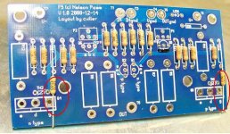
You'll notice in the picture that I've placed the grid oops! gate
stoppers as close as I could as per EUVLs suggestion many
posts back. Don't want dem os-kelations startin' up.
I've got the half watters placed on two of CVillers boards.
Tommorow, I'll select/matchup the 0.47 & 100 Ohm source &
feedback 3 watters and place them. Check the placement a
second time vs. the schematic then shoot the lead to 'em.
You'll notice in the picture that I've placed the grid oops! gate
stoppers as close as I could as per EUVLs suggestion many
posts back. Don't want dem os-kelations startin' up.
Attachments
bobodioulasso said:Cviller
i would like to order two F5 PCB but , as it is my first post in this forum though i read it for a while, i can't email you. May be you could email me instead? It seems that i need your email adress to send you a payment with paypal. Do i need to fill the wiki too?
You don't have email activated so I cannot write to you, but you can find my email address on the wiki in my signature.
ichiban said:
You'll notice in the picture that I've placed the grid oops! gate
stoppers as close as I could as per EUVLs suggestion many
posts back. Don't want dem os-kelations startin' up.
Looks like this is going to be a really nice build! 😀
I bet you are more likely to get oscillations if you place the gatestoppers dangling... and if you do get oscillations in this amp, it would most likely be due to incorrect wiring.
@ Fran - have you possibility to look at output ( with setup as is - cables , source) with CRO ?
seems that you have oscillations , and not having current limiter parts doesn't help you with this ......
seems that you have oscillations , and not having current limiter parts doesn't help you with this ......
Yes, I have an oscilloscope but I'm not sure exactly how to use it. If you can tell me exactly what to measure I can do that ok.
Source into the amp is from a 24V aikido pre (with output caps) and The gate stoppers are mounted right on the gate of the mosfets.
Will set up and take the measurements tonight.
Fran
Source into the amp is from a 24V aikido pre (with output caps) and The gate stoppers are mounted right on the gate of the mosfets.
Will set up and take the measurements tonight.
Fran
One other thing.... all of this setup works fine with my other amps.... so I'm kind of ruling out source or speakers as the problem.
EDIT: Would it be ok to attach a dummy load to the outputs rather than hooking up my quads? I really wouldn't like to damage them.
Fran
EDIT: Would it be ok to attach a dummy load to the outputs rather than hooking up my quads? I really wouldn't like to damage them.
Fran
woodturner-fran said:One other thing.... all of this setup works fine with my other amps.... so I'm kind of ruling out source or speakers as the problem.
EDIT: Would it be ok to attach a dummy load to the outputs rather than hooking up my quads? I really wouldn't like to damage them.
Fran
I would just let the amp run with no speakers connected until it stabilizes.
- Home
- Amplifiers
- Pass Labs
- F5 power amplifier