Dougie085 said:What do you think the minimum size transformer should be for a monoblock? Would something like 250va work or something? I was wondering because I want to try and fit these into a chassis thats going to be relatively small.
That should be OK. I use CNC tooling transformers from Antekinc.com
This is iteration V2 of the previous layout (post 235) now we have the FET’s spread out that may suit other builders.
If some one is interested in building any of the two versions just PM me and I will prepare pdf files suitable for etching.
Though pin marks are correct please take in consideration that the case outline of Q1 or Q2 could be reversed on one of those since I didn’t look up the spec sheet.
Read also post 263 for other details.
Attachments

Darren,
The file shown is not to scale so I wouldn't do that.
On the other hand I'm doing some slight changes to acommodate 4 screw holes needed plus widening the rail traces a bit. But the good news is that it's finished.
I will prepare now the pdf's 😉
The file shown is not to scale so I wouldn't do that.
On the other hand I'm doing some slight changes to acommodate 4 screw holes needed plus widening the rail traces a bit. But the good news is that it's finished.
I will prepare now the pdf's 😉
Well was going for like a 6x6" monoblock but I'm not sure I can fit everything into that size chassis. I'll have to play with the design a bit.
Tony,
I'm very excited. This project presents several first for me, one of which is etching the circuits. I have done a small PS board via hand transfer, but this will be breaking new ground. Thank you kindly for sharing your work. Another big thanks to you, Mr.Pass.
7/10
I'm very excited. This project presents several first for me, one of which is etching the circuits. I have done a small PS board via hand transfer, but this will be breaking new ground. Thank you kindly for sharing your work. Another big thanks to you, Mr.Pass.
7/10
How much is the acid and PCB material to etch pcb's? I really like the nice clean look of a PCB so I may try and etch those boards that apassgear posted they look very nice. Also does anyone have etching files for the ZV5 PSU board? If not I may take a stab at it. Do you guys use Eagle or something for the board layouts?
Re: Hi!
Rider,
Those are thermistors nothing more than variable resistors shown on Nelson's schematic. Their value is 4.7K Ohms. They should be instaled on the heatsink near the FET's. In this aplication they work as temp compensation devices.
Do a google to learn more about them.
zeonrider said:@apassgear, tell me more about TH1/TH2!
thanks.
Regards zeoN_Rider
Rider,
Those are thermistors nothing more than variable resistors shown on Nelson's schematic. Their value is 4.7K Ohms. They should be instaled on the heatsink near the FET's. In this aplication they work as temp compensation devices.
Do a google to learn more about them.
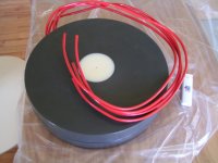
I sure hope I'm doing this right. I've got 145 ft, of 14ga THHN per coil. 3.75in of air core. 6in overall, 120 turns and a weight of 2.25lbs ea.
Seventenths -- Please let us know how this works--I always assumed it would not work well, since the insulation is pretty thick. But if this assumption is incorrect it would be good to know!
What do you think the minimum size transformer should be for a monoblock? Would something like 250va work or something?
I like to keep a 4-1 margin of excess. ie 20volts x 2amps = 40VA, x 2 rails = 80VA x 4(margin of excess) =320VA. This would be for one channel assuming you have +/-20 Volts output and draw 2 amps from each rail(no, I don't know the exact figures for the F5).
I have had significant transformer hum when using a 2X margin of excess. A 400VA trafo is probably $20 more than a 250VA trafo--it could save you some headaches down the road.
JJ
jupiterjune said:
Seventenths -- Please let us know how this works--I always assumed it would not work well, since the insulation is pretty thick. But if this assumption is incorrect it would be good to know!
JJ
The only drawback in this application, is the fact that you will see higher DCR for a given inductance, and naturally the inductors will turn out much bigger.
Counting out those issues, it works just fine.
Personally I would wrap those inductors with some sort of textile, in order to keep them from vibrating.
Magura 🙂
Thank you magura! I will heed your advice. The calculated DCR was ,4r and the actual measurment i get is ,5r
I guess I'm at least in the ball-park.
And BIG, yes. The transformers and inductors weigh in at a combined 27 pounds 🙂 9lbs for coils and 18 for transformers.
On to the PCBs...
7/10
I guess I'm at least in the ball-park.
And BIG, yes. The transformers and inductors weigh in at a combined 27 pounds 🙂 9lbs for coils and 18 for transformers.
On to the PCBs...
7/10
seventenths said:
And BIG, yes. The transformers and inductors weigh in at a combined 27 pounds 🙂 9lbs for coils and 18 for transformers.
7/10
No worries, as long as the copper was for free 😀
The pic is of an inductor I recently finished, note the lighter😀
These weighed in around 50 lb a piece 🙄
Magura 🙂
Attachments
seventenths said:Thank you magura! I will heed your advice. The calculated DCR was ,4r and the actual measurment i get is ,5r
I guess I'm at least in the ball-park.
And BIG, yes. The transformers and inductors weigh in at a combined 27 pounds 🙂 9lbs for coils and 18 for transformers.
On to the PCBs...
7/10
Did you wind your own transformers?
Did you measure with a 4 Point measurement? Typically a handheld will be about 1 ohm with the leads shrted togetherseventenths said:... The calculated DCR was ,4r and the actual measurment i get is ,5r...
7/10
😉
- Home
- Amplifiers
- Pass Labs
- F5 power amplifier