jam said:This is what I was proposing as a higher powered version of the A5...............of course Mr.Pass's more sophiscated biasing and feedback network could be and (should ) be used.
Jam
I just complete amp close to this design last night. It starts to sign but with too much ofset. It reach +/- 80mV.

Time to fix it out.
I followed a link from a "inductor winding tips" thread to a calculator and proceeded from there.
Oh and the reason I'm winding my own
1. I'm in this for the journey... mostly
2. I have a thousand feet or so of unused solid conductor cable and a desire to get started 😀
I sure hope I'm doing this right. I've got 145 ft, of 14ga THHN per coil. 3.75in of air core. 6in overall, 120 turns and a weight of 2.25lbs ea.
I'm beginning to appreciate the "gravity" of things 🙂
7/10
Dougie085 said:Well how do you measure the inductor to make sure its right.
seventenths said:I followed a link from a "inductor winding tips" thread to a calculator and proceeded from there.
Oh and the reason I'm winding my own
1. I'm in this for the journey... mostly
2. I have a thousand feet or so of unused solid conductor cable and a desire to get started 😀
I sure hope I'm doing this right. I've got 145 ft, of 14ga THHN per coil. 3.75in of air core. 6in overall, 120 turns and a weight of 2.25lbs ea.
I'm beginning to appreciate the "gravity" of things 🙂
7/10
Any comments on capacitance between windings??Insulated wire might cause undue reactance ??. I cant remember....Hell to be old and

sandstorm33 said:
Any comments on capacitance between windings??Insulated wire might cause undue reactance ??. I cant remember....Hell to be old and

No comment.err hum uh...
I posted a thread in regard to using this particular wire for inductors and on the strength of a single reply from a well qualified respondent , I forged ahead. If it turns out to be problematic, I'll go with plan "B". No worries.
I am, however, quite interested in hearing other opinions.
cheers,
7/10
Standing on the shoulders of giants...
Excuse my ignorance, but is THNN insulation another name for standard enamelled transformer wire or some other type? [The winding programs generally only apply to enamelled wire.]
jameshillj said:Excuse my ignorance, but is THNN insulation another name for standard enamelled transformer wire or some other type? [The winding programs generally only apply to enamelled wire.]
I believe the wire here is THHN which is a premium grade building wire with a high temp plastic insulation. This why the coil in question is 6 inches in diameter as compared to a 3inch dia. magnet wire equivalent.
Years ago I made coils with cotton covered wire that were successful so who knows ???May work just fine.😕
Don't think you'll get a lot of inductance but still should do a reasonable job - hell of a fight with 14# plus insulation - let's know how it turns out.
Can also add some metal here for power supply chokes but may need "snubbers" to stop current pulse ringing.
Can also add some metal here for power supply chokes but may need "snubbers" to stop current pulse ringing.
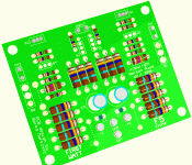
bogdan_borko said:I`ve been working on the F5 pcb for some time and this is my version. (This is "3D" view from Protel).
naah ..........
too green !
(fugly!)

and let me tell you, those pots are "titchy"
An externally hosted image should be here but it was not working when we last tested it.
Honestly... I don't know 🙂 , but I did see a method of measuring inductance without an LCR meter. I'll try it in a bit.
It's kind of a PITA and I've made 2 of 4 so I sure hope it works as planned. We will see...
7/10
It's kind of a PITA and I've made 2 of 4 so I sure hope it works as planned. We will see...
7/10
In a few weeks I'll probably order parts for this amp. The amp I currently have is a chipamp and it belongs to my friend. He just never had time to finish it. I have to get the design of the chassis down so I can go by this place and get the pieces cut. Hopefully have the chassis done by time I can order the parts to build the amp.
When powering this thing up you may want to use a simple LM317/LM337 current limiter set up for 1.2A -- (NP suggests a 1A fast-blow fuse --you'll go through a lot of these)
I set the amplifier up first on a PS5010 bench power supply where 400mA is the limit. Once you get each side to idle at 400mA with 24V you can go to a supply which will provide 10A peak/6A continuous as recommended in the AX article. You just have to be patient. The LM317/337's should be heat sinked, and you will lose some voltage across them.
I set the amplifier up first on a PS5010 bench power supply where 400mA is the limit. Once you get each side to idle at 400mA with 24V you can go to a supply which will provide 10A peak/6A continuous as recommended in the AX article. You just have to be patient. The LM317/337's should be heat sinked, and you will lose some voltage across them.
- Home
- Amplifiers
- Pass Labs
- F5 power amplifier

