I have lots of caps on hand of various types and I hate to put in an order for one item from Digikey...
If you mail in a check to Digikey for the parts total plus your state sales tax, the shipping is free.
No minimum order.

The exact value isn't too important; I've used parts from 2200pF to 4700pF in various builds.
If there are electronic supply stores in your area, by all means check them out. I recall seeing some in a surplus store in Toronto (sadly closed a few years ago).
If there are electronic supply stores in your area, by all means check them out. I recall seeing some in a surplus store in Toronto (sadly closed a few years ago).
Last edited:
I need to substitute for a ZTX450 that I accidentally destroyed. I have MPSA18 on hand, which I believe I can use for this purpose. Since I'm new at this, a couple of questions: 1) Can I substitute MPSA18 for one of the ZTX450 transistors on the F5 boards? 2) If I can, it appears that the orientation of the MPSA18 is the same as the ZTX450, with the flat side facing the pot, and collector-base-emitter running left to right. Is that correct? 3) If I can, should I substitute MPSA18 for both boards, or is it okay to leave the ZTX450 on the other board? (In other words, will different transistor types in each channel lead to channel imbalances, etc?) Thanks.
bipolar transistor in F5 are "just" limiting parts
so, you can use practically any small bjt in similar case with similar characteristics
so called TUN and TUP - transistor universal N, transistor universal P
so, you can use practically any small bjt in similar case with similar characteristics
so called TUN and TUP - transistor universal N, transistor universal P
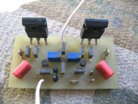
Today I hocked up an F5 with Toshiba power mosfets and 2SK170BL & 2SJ74BL based on Zen Mod circuit.
I used 0.22 5W power resistors instead of 0.1 10W, that what I had at hand. (??) Zen should I change those?
Thank you Zen for the circuit. It is working!
The other-side in the amp my old ProFet DIY with Exicon mosfets and Caddock resistors.
Please do not ask witch sounds better!
Too early to compare them.
The supply voltage only 18V DC at the moment. I will have to use some higher V toroidal.
Only I have at hand 20V-0-20V 500VA it may be the V to high for the smaller Toshiba power mosfets.
Attachments
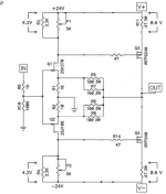
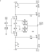
Sorry Zen I do not find you Shematics. It is similar to this but a bit different. had 0.1 10W resistors.
I Just see that schematic 1 or 2 days a go. The F5m.
Yes right now everything needs to be bigger, higher rail voltage, bigger heat-sink so on.
Originally that was and still my DIY ProFet amp ( from time before F5).
That amp a bit more sensitive with my speakers and was loud enough in Stereo.
I re-draw the circuit just as it is now.
Unfortunately I forget to save yours and the one I posted previously just was close to that but not equal.
Attachments
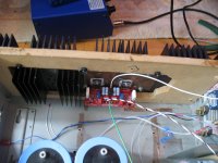
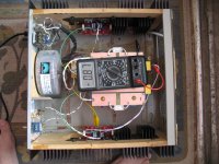
Coming together slowly and nicely. This heatsink has bigger surface and almost 1Kg more weight than the previous was.
Of course I will go a bit higher power 24-0-24 VDC rail voltage. If is too much on the Toshiba mosfets I will turn down the bias a bit.
This heatsink handled easily the Hiraga Class A at 1.1-1.2 A @ 24-25 V rail voltage.
Should be good enough for this little amp.
Zen should I use all 4 Pc of Mallory 62 000 uF capacitors for this amp or two of those will do it and ad two smaller like 10 000 uF so I can have C-R-C type of PS??
Attachments
first try just one Bigun per rail
if there is some hum, add 10mF as first in CRC, leave Bigun last in rail
if there is some hum, add 10mF as first in CRC, leave Bigun last in rail
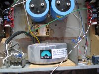
First power up the power supply.
I will let it under power the next 10-20 hours.
Those caps were in the closet for more than a decade and when I purchased them they were already new old stock.
I do not have any soft starter neither a thermistor at hand.
500VA transformer with 4PC 64 000 uF Mallory caps.
If the transformer buzz when I start up under load I will (order) use some soft starter.
I learnt 500VA transformer (and Class A load) is the limit without soft starter after advised to use something.
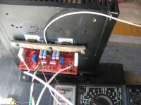
I went with all four caps because I only has two shackle, so I resolve using a piece of PCB,
If I had the ad two more caps I would need to modify the mounting. Hopefully it does not hurt a bit more uF.
Tomorrow I will power her up. Hopefully no smoke.
I will let it under power the next 10-20 hours.
Those caps were in the closet for more than a decade and when I purchased them they were already new old stock.
I do not have any soft starter neither a thermistor at hand.
500VA transformer with 4PC 64 000 uF Mallory caps.
If the transformer buzz when I start up under load I will (order) use some soft starter.
I learnt 500VA transformer (and Class A load) is the limit without soft starter after advised to use something.
I went with all four caps because I only has two shackle, so I resolve using a piece of PCB,
If I had the ad two more caps I would need to modify the mounting. Hopefully it does not hurt a bit more uF.
Tomorrow I will power her up. Hopefully no smoke.
Attachments
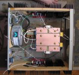
Not as easy!
One channel (the same was tested previously with lower voltage and with a smaller heatsink) up and biased.
After 1.5 hours later it settle the bias is 1.04 A at 27 VDC rail voltage.
One side connected to the PS only.
After the bias stabilized I thought time to set up the other channel.
Unfortunately it blew the 5A fuse, I used a bigger 8A.
The bias only was like 90 mA for some reason and after a half minute or so the feedback resistors got very warm, started to smoke.
I tried one more time if I adjust the trimmers (I can) but the smoke is there unfortunately. I have to disconnect that channel and check that closely. Maybe change all the semiconductors so on.
Unfortunately I'am not setup with a scope but hard to think about scope when the smoke slowly comes from the feedback resistors.
At both channel both of the trimmers were set up to the same value!
Something fishy there.
Now I leave it, it is Sunday, next week I will continue. Maybe I get some advise from some fellow DIY-ers.
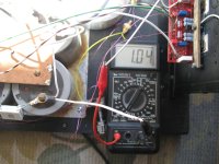
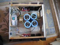
The picture was taken after 1/2 our warm up.
One channel (the same was tested previously with lower voltage and with a smaller heatsink) up and biased.
After 1.5 hours later it settle the bias is 1.04 A at 27 VDC rail voltage.
One side connected to the PS only.
After the bias stabilized I thought time to set up the other channel.
Unfortunately it blew the 5A fuse, I used a bigger 8A.
The bias only was like 90 mA for some reason and after a half minute or so the feedback resistors got very warm, started to smoke.
I tried one more time if I adjust the trimmers (I can) but the smoke is there unfortunately. I have to disconnect that channel and check that closely. Maybe change all the semiconductors so on.
Unfortunately I'am not setup with a scope but hard to think about scope when the smoke slowly comes from the feedback resistors.
At both channel both of the trimmers were set up to the same value!
Something fishy there.
Now I leave it, it is Sunday, next week I will continue. Maybe I get some advise from some fellow DIY-ers.
The picture was taken after 1/2 our warm up.
Attachments
When I tried to use the trimmers only one is working, slowly I increased (turn off, adjust and turn back on) the bias to 230mA. After even that trimmer stopped and now I got 0 mA bias.
I removed that side (channel) check everything with a jewelry magnifier all soldering intact, all resistors are good.
Very likely semiconductor(s) faulty.
If I can guess it is the JFet because I got some bias.
Trimmers were measured and both and good.
So I will start replacing all the semiconductors (have some extra at home).
I hate when need to tweak to find the problem, I gave up many project because of that.
I do not plan to give up this!
Next week with fresh enthusiast it will be resolved, hopefully.
- Home
- Amplifiers
- Pass Labs
- F5 power amplifier