

I see the differences on psu PCB . Photos from guide View attachment 733449View attachment 733450
That jumper is in place, it's the black wire on the left.
Bias voltage is a little out of balance, it's .664v and .665v on one channel, .684 and .685 on the other not warmed up. Offset is 1.4mv and 6.7mv.
If this is happening when starting up after being off for only a short time this could be normal. The thermistors only work when they have time to cool down.
If I immediately turn off and turn back on my F5 it will blow a 4A slow blow. But I have more transformer and caps.
If I immediately turn off and turn back on my F5 it will blow a 4A slow blow. But I have more transformer and caps.
You’re using “slow blow” fuses...right?
Yes.
@MaQuaide
Do have access to a clamp meter?
Nope. If I did how would I use it?
I had a nice chat with 6L6 and we think it's OK working with a 4a fuse, but will keep an eye on it. He also sent me this thread.
https://www.diyaudio.com/forums/pas...-usa-160w-class-watt-designs.html#post5634640
Nope. If I did how would I use it.
That's a really good question...I have one but have not actually used it on a FW amp. I'm thinking it would be clamped on the + of the mains inlet inside the chassis and set to "peak hold" to measure inrush current. After that it could be used to measure normal operating current draw.
I'll try it and report back.
Alright...setting the meter to peak hold it read 1.95A at start up. Resetting and testing again I got 1.4A at idle. I'm using a 400VA transformer and a total of 80,000uF. An M2 board is plugged in at the moment.
Yes I'm using CL60's
Yes I'm using CL60's
Last edited:
I'm using 3 amp fuses in an F5 with a 600VA toroidal with dual 24V secondaries feeding 120,000uF of caps. Never popped a fuse with cold CL60's. It'll pop a fuse in a heartbeat if the CL60's are at all hot. That power is going somewhere and I'd be pretty curious where.
I'm using 3 amp fuses in an F5 with a 600VA toroidal with dual 24V secondaries feeding 120,000uF of caps. Never popped a fuse with cold CL60's. It'll pop a fuse in a heartbeat if the CL60's are at all hot. That power is going somewhere and I'd be pretty curious where.
I think the cause is an intermittent AC connection from the PEM. I'll get rid of the crimped quick disconnects and solder the connections.
Well this is embarrassing, the CL60s were bypassed since I built the amp. There were two plates on the terminal block making the CL60s redundant. My first clue was they were generating no heat. They now heat up and the PS lights up more gently.
Was this doing damage to the amp other than blowing fuses? 😕
Was this doing damage to the amp other than blowing fuses? 😕
Well this is embarrassing, the CL60s were bypassed since I built the amp. There were two plates on the terminal block making the CL60s redundant. My first clue was they were generating no heat. They now heat up and the PS lights up more gently.
Was this doing damage to the amp other than blowing fuses? 😕
No damage. Its hard on the caps, but not a big deal.
BTW, don't touch a CL60 with your hands if that's what you were doing. It's full of line voltage and one nick in the insulation or touch of the uninsulated lead and...
Also, if you are trying to bias the amplifier to a specific value you may need to rebias it. The thermistor makes the line voltage a little lower, which makes the rail voltage a little lower. Which makes the bias a little lower.
Thanks, I have an infrared thermometer and an aversion to touching live components.
 I had it biased a little hot anyway.
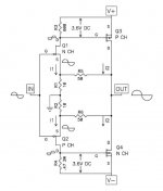
Yes and no. Without potentiometers front he rails to the Jfets, you'll have no way to set operating points and offset. That simplified schematic is only a few parts simpler than the real circuit... might as well make the F5 and use a smaller PSU for your target power output.
hello, what is the jfet dissipation in an F5 / F5 turbo v1 without cascode?
it seems to me that I current chosen was 6mA for an idss of 8mA ?
thanks
it seems to me that I current chosen was 6mA for an idss of 8mA ?
thanks
Dissipation is the current times the voltage.
For example 6 mA x 30 volts = 180 mW. The 30V would typically come from a
supply of about 34-35V, subtracting 4 or 5 volts across the Drain load resistor.
For example 6 mA x 30 volts = 180 mW. The 30V would typically come from a
supply of about 34-35V, subtracting 4 or 5 volts across the Drain load resistor.
Hello Mr. Pass, thank you for your answer
In fact i asked my question incorrectly.
What I would like to know is the maximum resonable dissipation that you recommend for JFet, and the percentage of current that we are supposed to reach compared to the Idss
Thank you
Best regards
Sebastien
In fact i asked my question incorrectly.
What I would like to know is the maximum resonable dissipation that you recommend for JFet, and the percentage of current that we are supposed to reach compared to the Idss
Thank you
Best regards
Sebastien
Last edited:
If the environment is room temperature, then 1/2 the rated dissipation is fine.
If the environment is hot, as in the interior of a Class A amplifier, then it
would want to be derated. The Toshibas originally used are 400 mW which is a
bit over that edge, but none have failed.
If the environment is hot, as in the interior of a Class A amplifier, then it
would want to be derated. The Toshibas originally used are 400 mW which is a
bit over that edge, but none have failed.
- Home
- Amplifiers
- Pass Labs
- F5 power amplifier