if you don't have shorty between two RCA hots , short is definitely between ears

😀😀😀
I finished the basic F5 a couple of years ago and really like the sound but felt that the imaging was lacking. Recently played it with a new pair of open baffle speakers for a friend and he said he thought the sound was mono. I got some test tones and sure enough when each channel was supposed to play by itself they both played and the sound was straight down the middle. So I started changing components and cables to isolate the problem. I tried an older receiver with similar results and then a third just for the heck of it and there was the stereo. At this point when using all my original setup, except the F5, I have stereo. It would seem that the F5 and also the second amplifier have a problem. I rebiased the F5, tried hooking up speakers out of phase, checked the star ground setup and as far as I can tell I have wired correctly. I am at a loss and wonder if anyone could give me some advice, aside from having my hearing checked so I might tell the difference between mono & stereo.
Maybe some pictures of the whole amp innards in one shot may be useful for chaps here to help diagnose. Your current shots are a bit too close to tell how both boards are hooked up.
Well, the output of either channel is the drain of the MOSFETs. Your case is all metal? Is it possible that you have one output shorted to the other through the Heat sink connection of the MOSFETs. An ohm meter check with ohms or vlotage should show this...
shortie from drain to sink/case means shorted fuse
sole possibility for mono setup is on input side ...... or pure short between outputs ( no case involved)
sole possibility for mono setup is on input side ...... or pure short between outputs ( no case involved)
I finished the basic F5 a couple of years ago and really like the sound but felt that the imaging was lacking. Recently played it with a new pair of open baffle speakers for a friend and he said he thought the sound was mono. I got some test tones and sure enough when each channel was supposed to play by itself they both played and the sound was straight down the middle. So I started changing components and cables to isolate the problem. I tried an older receiver with similar results and then a third just for the heck of it and there was the stereo. At this point when using all my original setup, except the F5, I have stereo. It would seem that the F5 and also the second amplifier have a problem. I rebiased the F5, tried hooking up speakers out of phase, checked the star ground setup and as far as I can tell I have wired correctly. I am at a loss and wonder if anyone could give me some advice, aside from having my hearing checked so I might tell the difference between mono & stereo.
It would help, as someone already said, to have a photo of entire amp inside so we could follow the wires.
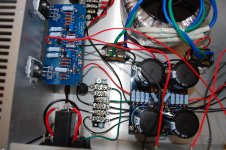
With that said, I don't get the grounding going on that terminal strip, several black and green wires tied together, then 2 terminals with black wires, not tied to ground, could be rail? I don't see a star ground and I bet somewhere you have a shared ground wire that is not really grounded.
It can be a problem having too few colors for wiring, rail voltage and grounding being black.
More photos,
Rush
I would check your interconnects, cabling towards the amp, maybe left and right are shorted there.
Is the case grounded? Is the output driving a thermister and a speaker?shortie from drain to sink/case means shorted fuse
sole possibility for mono setup is on input side ...... or pure short between outputs ( no case involved)
If the output is a 0.0V why would the fuse blow?
More photos
The shorty between the ears I have been aware of for quite some time, thank you. Just a few more photos I have on hand that may be useful. I can zoom in on anything that anyone wants to see. The grounding scheme I was trying to emulate is in the drawing below. I returned the speaker return to the pcb and then to the terminal strip, although I see the prefered method would be to go directly to the strip. I was thinking of the strip as a star ground. The chassis is grounded to the strip by one of the fastening bolts. A visual check of the rca jacks looks good to me. I don't have any good shots of them to upload at present.
The shorty between the ears I have been aware of for quite some time, thank you. Just a few more photos I have on hand that may be useful. I can zoom in on anything that anyone wants to see. The grounding scheme I was trying to emulate is in the drawing below. I returned the speaker return to the pcb and then to the terminal strip, although I see the prefered method would be to go directly to the strip. I was thinking of the strip as a star ground. The chassis is grounded to the strip by one of the fastening bolts. A visual check of the rca jacks looks good to me. I don't have any good shots of them to upload at present.
Attachments


I finished the basic F5 a couple of years ago and really like the sound but felt that the imaging was lacking. .
Hope this problem will be resolved. The internal arrangement of your amp is admirable.
The thermistor and its location caught my eye. I had this [silly] idea to share with y'all. The gate lead is part of the semiconductor die, and thus is hot [thermally]. I suggest to relocate the thermistor circuit [2.21 K and TH1] after the 47 Ohm such that one lead of the thermistor is soldered directly to the gate lead, and as close to the plastic body of the Mosfet as possible. This way, the thermistor receives thermal energy by direct conduction, and also via its body as originally intended. Potentially a simple approach to further improve the thermal stability of diyF5.
Thanks 6L6. I was thinking of trying that (pulling an rca cable). I'll set up a simple system this evening of CD player, F5, and speakers and try a few things.
Walter W I don't think the problem is the cabling since my complete original system plays in stereo nicely with the F5 removed and replaced with another amplifier .
Walter W I don't think the problem is the cabling since my complete original system plays in stereo nicely with the F5 removed and replaced with another amplifier .
That wiring diagram hurts old eyes 🙂 but it looks more or less correct.
The only possibilities I can think of are that the outputs are shorted to each other, that the input grounds are miswired and you are hearing only the difference between channels, or that somehow you have something very funky going on with the power supply. For example, I see absolutely no soldered points on the positive supply board, the two boards are supposed to connect to each other through their ground terminals and that becomes supply ground, it looks like only one of them is hooked up to the ground terminal block.
The only possibilities I can think of are that the outputs are shorted to each other, that the input grounds are miswired and you are hearing only the difference between channels, or that somehow you have something very funky going on with the power supply. For example, I see absolutely no soldered points on the positive supply board, the two boards are supposed to connect to each other through their ground terminals and that becomes supply ground, it looks like only one of them is hooked up to the ground terminal block.
I agree. At idle, the steady state heatsink temperature is 50 Celsius. The heat source MOSFET package and its 3 leads can only be at a similar temperature. Touch the source and drain leads to test. Touching the gate lead may introduce hum!The drain lead (middle) is the metal face of the transistor, not the gate.
That wiring diagram hurts old eyes 🙂 but it looks more or less correct.
The only possibilities I can think of are that the outputs are shorted to each other, that the input grounds are miswired and you are hearing only the difference between channels, or that somehow you have something very funky going on with the power supply. For example, I see absolutely no soldered points on the positive supply board, the two boards are supposed to connect to each other through their ground terminals and that becomes supply ground, it looks like only one of them is hooked up to the ground terminal block.
Yes, I think a jumper is missing between the supply boards and the pos rail must be floating. I could be missing it, but is there more than one ground wire going to the amp boards? It looks to me that the only ground is the input from the RCA. Try star grounding the RCA and the boards, don't daisy chain any grounds.
Rush
Take a look at the left picture of the amp's internal layout. Mentally remove the left channel [as you see it] and piggyback it on the right channel [as you see it] . The right channel shows a black wire at the top left of its pcb. By contrast, the left channel shows a red wire instead. Wiring confusion, and a possible problem. The pcbs as they sit in the picture are not mirror images! With all due respect to the builder, 4 different color wires to the pcb are preferred instead of only red and black.
Last edited:
The white paste is Zinc Oxide [ZnO] in a viscous Silicone fluid. ZnO is a heat but not an electrical conductor.It really looks like the paste would be shorting over the mica.
Point taken regarding using four colors wire. I apologize for the difficulty in checking the wiring. I will try in the next few days to come up with a diagram showing the hookups.
I tried pulling the rca input cables. With the left pulled my test tone CD started with a voice through both channels announcing the test. The test tone for the left channel was silent. The test tone for the right channel played through both channels. Pulling the right cable produced the opposite result.
I appreciate the response I have gotten on this problem. I will work through all the suggestions and observations made over the next few days. Thank you.
- Home
- Amplifiers
- Pass Labs
- F5 power amplifier