Progress!
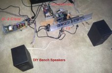
The F5 test rig build sounds great with the addition of a preamp. I used a JC-2 clone built from an ebay kit that has a tendency to slightly sweeten anything it pushes without adding any distortion. I have a Carver C-1 to try but I don't think it will perform any better.
Bias at 0.59V and DC offset at 0.0-1 are stable with ~ 12 hours of use. Not sure about burn-in on an amp without caps but it seems to sound a little warmer with use.
Next step - the box.
Attachments
I suspect Pass determined the lowest gain the F5 could be used at, without needing separate compensation components when built using his recommendations.
Increasing the stability margins by increasing the gain can lead to a "flat" sounding amplifier. But since this is a PASS design I suspect there are a range of acceptable gain settings that all sound good.
Thanks, yes I plan to have a variable feedback possibly but within acceptable parameters 🙂
Another newbie question, i would like to add VU meters to my F5 well F5T
do you think theres any way the ones here would make the F5 sound worse ?
and is there any compatibility problem ive missed?
2xPanel VU Meter DB Meter+Driver DIY Assembled fr T AMP | eBay
Thanks, yes I plan to have a variable feedback possibly but within acceptable parameters 🙂
Be careful if you are planning to use potentiometers, you need wattage that is defined in the schematic (at least).
I would recommend to use swappable power resitors and check the parameters (bias, DC offset) after swapping you could ruin your speakers in the case of a fault.
Regards
Floric
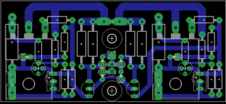
Got 2 F5 amplifiers running now. one with a shared toroid in a Hifi2000 case, very neat and tidy and that one has been sold. Another one for myself with dual E-core built on de back of an old JBL 6290 heatsink including transformers. Used my own PCB design because i thought it could be smaller (this is 76x34mm) and only needed one layer. Dual layer is too much for such a simple design. Keeping traces short (enough) helps a lot.
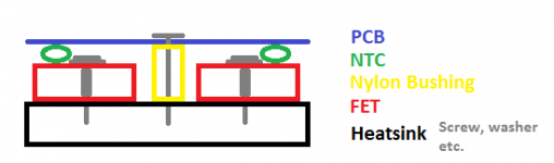
The NTCs and FETS are on underside of the PCB, rest is on top.
The 2 holes in the middle are there to hold the PCB tightly down, pressing the NTCs to the FETs. By using nylon bushes around these screws as spacers the same thickness as the NTCs+FETS together I get the best thermal coupling without bending the PCB.
The sound? I think the F5 has the best sound i've ever heard. It's musicality while keeping detail and definition at the highest levels is simply unbeatable.
I've got a Sony N77ES, some Accuphase beast, Moon, Rega and a borrowed Lyngdorf TDAI2200 and a whole list of other amplifiers to compare it with. Some are better in terms of absolute control. Most of them.. have flaws. But
None are better at music. With the F5, it just sounds right.
Attachments
Helping my friend power up his F5 today, we ran into an immediate problem.
He has Peter Daniels tiny boards, that I meticulously populated myself, with the full circuit, and the original resistor values from the earliest schematic publication.
The power supply was tested prior to power up, and was reading 26.2v & -26.1v, but once connected to the amp board, for power up, was reading 19.2v & -19.2v.
The Problem:
On power up, across R11 & R12 values were reading 1.8v DC on both channels. Both P1s and P2s were set until clicking fully anti-clockwise. We did not test the speaker outputs yet, as we only have 2 multimeters, and we already had a power down problem. Searching the boards etc, yielded nothing but scratched heads. Can anybody help?
Many thanks
Lucas
Lucas you need to set P1 & P2 so that you have the lowest possible resistance across R5 & R6 then adjust each trimmer by half a turn alternately until you start getting readings across the source resistors.You think that nothing is registering then they suddenly show a reading so slowly does it.Good luck.
Both P1s and P2s were set until clicking fully anti-clockwise.
try measure on paralel resistor (R3/R4)....(no power on)
On the Peter Daniel boards the pot orientation is different from the cViller boards, IINM. One pot rotates in the opposite direction, don't remember which. If you want both to be rotated in the same direction the wipers have to be mirror-imaged.
Ideally you want to measure the resistance after the pot is in circuit, and check that the pot shows zero reading in power off mode.
Ideally you want to measure the resistance after the pot is in circuit, and check that the pot shows zero reading in power off mode.
I always query the standard multi-turn pot orientation in a pre-made PCB.
I try to determine which direction of rotation is required to make the parameter increase. I then orient the pot such that "clockwise" = increase in parameter.
I never accept that the PCB designer's criteria are the same as mine.
I try to determine which direction of rotation is required to make the parameter increase. I then orient the pot such that "clockwise" = increase in parameter.
I never accept that the PCB designer's criteria are the same as mine.
The power supply was tested prior to power up, and was reading 26.2v & -26.1v,
Good.
The PSU is sagging under a large load. (That's actually normal...)but once connected to the amp board, for power up, was reading 19.2v & -19.2v.
That is three times the recommended bias current!😱😱😱On power up, across R11 & R12 values were reading 1.8v DC on both channels.
And also why the PSU is measuring so low...
Nobody said anti-clockwise on the trimmer pots was 'down' --Both P1s and P2s were set until clicking fully anti-clockwise.
Quite simply, you have the bias turned all the way up. 🙂
As Marra suggested, with the power off measure resistance across R3 and R4, and turn the pot until it reads the minimum amount. Then the pots should be all the way 'down'
You could also mark (with a small arrow) the pot face with the 'up' direction of rotation.
capacitors
Hello,
I've got almost all the parts to build an F5. Actually, I am building Juma's variation... but posting here because many more eyes.
http://www.diyaudio.com/forums/pass-labs/168040-f5-2sk2013-2sj313.html
My question is about limiting the bandwith. I am building this amp with a lot of spare parts that I already have, including a Vicor switching supply (pretty good one.) I also live about 200m from three AM radio antennas.
Now, I haven't had a ton of problems with other equipment that I built, but I would prefer to play it safe and limit the bandwith a bit.
I've seen posting on this thread of 1-3nF across the feedback resistors R5/R8, but it seems that was mostly to prevent overshoot, more than anything.
1) What size capacitors would someone recommend across the feedback resistors and/or the input jfets?
2) Is matching/ and or specific type of cap imperative?
Forgive me if this question has been asked here, but I could not find it with a search.
Thanks
If the local AM RF power is a problem then I suggest you fit both differential and common mode attenuators.
I also suggest you use good RF screening chassis.
I also suggest you use good RF screening chassis.
1) What size capacitors would someone recommend across the feedback resistors and/or the input jfets?
2) Is matching/ and or specific type of cap imperative?
In the F5Turbo article Nelson suggests 1000pF (0.001uF) from gate (before the gatestopper resistor) to output, or across the feedback resistors. You can see them if the F5T article on the V3 schematic - http://www.firstwatt.com/pdf/art_f5_turbo.pdf
I have had fatal oscillation problems with the F5T -- that cap, in addition to 680R gatestoppers, solved it.
Don't worry about type of cap, whatever you have on hand will be fine.
Thanks! It was hard for me to locate that information, but there it was!
In the F5Turbo article Nelson suggests 1000pF (0.001uF) from gate (before the gatestopper resistor) to output, or across the feedback resistors. You can see them if the F5T article on the V3 schematic - http://www.firstwatt.com/pdf/art_f5_turbo.pdf
I have had fatal oscillation problems with the F5T -- that cap, in addition to 680R gatestoppers, solved it.
Don't worry about type of cap, whatever you have on hand will be fine.
.... I....live about 200m from three AM radio antennas.
This is outside the realm of your posting, but have you considered wearing copper boxer shorts, with a good grounding strap to your left shoe's soul?
...😱
I also live about 200m from three AM radio antennas.
Just build a BIG loop antenna and bury it in the garden, free power 😀


This is outside the realm of your posting, but have you considered wearing copper boxer shorts, with a good grounding strap to your left shoe's soul?
...😱
Already do that... but its always been more for style than anything else😀😎
- Home
- Amplifiers
- Pass Labs
- F5 power amplifier