Sa y you do stock F5
CRC for suply ad a cable CR + resistance of cableC
the R is there for reducing riple so you get riple reduction for "FREE"
but you need the last bank of caps near the mosfets as you need lowest possible impedence on the suply to cope with demand from eletronics.
If you do CRC + cable you may end up with lack of juce when the amplifier wants it
Current clipping is as baaad as Voltagge clipping if not worst
I see what you mean. At what cable length does this really matter? I plan to set amp right on top of power supply, the cable added is only about 11". I can certainly add caps there is a lot of room on the amp chassis, just not something I thought about before. How big do the caps need to be? I've got 90,000uf per rail now, 6 x 15,000uf. I have some extra, would those be good?
Thanks,
Jim
Thanks,
Jim
Cable lenght wont make much difference in your case.
My cables would have to be 15 feet or there about so big difference there
Was only joking about FREE riple reduction as cable is realy expensive
To be onest I rather have them shorth or none at all. Just my romm lay out and her dictates.
About the caps at 90mF you are hitting point where law of diminishing returns aply.
Maybe you could try 30mF goups in CRCR+cableC
The more the better but over a certain point improvment/cash get smaller and smaler.
If you already have them split the last R bank so each channel has its own.
I have to do this as I have 2 separate enclosures for the 2 channels
___________30 Left
Say 30R30R
___________30 Right
Like you I went for smaller 10mF (40 of them)IMO beter and faster than 8X50mF ones
I started up with 150mF but only because cheap and nasty caps price breack was good.
Now that I have eard how good the F5 is I have already ordered beter quality ones.
Also cek Papa suply articles he reccomends to use a few smallers ones to speed up things just a few uF on the last bank of real good quality Panasonic if I remember
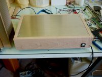
F5 finally (almost) complete. It needs some polishing and a chassis cover, but it is already hooked up to my main system anyway. Best sounding amp I have built and totally quiet.
It is quite revealing (amazed at how many truly terrible recordings there are), but the good ones sound soooo good.
Many thanks to Mr. Pass and cviller!
It is quite revealing (amazed at how many truly terrible recordings there are), but the good ones sound soooo good.
Many thanks to Mr. Pass and cviller!
Attachments


More F5 Images
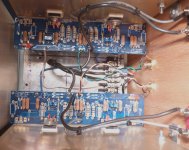
Nicely done! Shouldn't you have the bias resistors mounted slightly higher off the pcb as they generate a considerable amount of heat?
I am Liking it
I Had exactley same impression listening to mine
Loads o records became realy baad especialy poor live stuff.
But real bliss whit others
What mosfets do you use?
And Bias/Voltagge look like yor sinks can take it and I am courious to know what you think about sound and dinamics at higher levels.
I Had exactley same impression listening to mine
Loads o records became realy baad especialy poor live stuff.
But real bliss whit others
What mosfets do you use?
And Bias/Voltagge look like yor sinks can take it and I am courious to know what you think about sound and dinamics at higher levels.
The bias resistors do have a bit of airspace beneath them, but good point-they could be mounted higher.
I used the IRFP240 and 9240.
I was paranoid about over heating, so I bought one of those infrared thermometers.
The mosfets read about 60C after 3 or 4 hours. The sinks are hot but I can easily "hold" onto them for > 10 seconds.
Haven't pushed the amp too hard. One thing I really like about it is it sounds great at low volume.
60 C is preaty good are those posh ceramic isolators under them?
Please don't be shy give as more about the sound
EG why low volume?
Found that a can't get enough and volume pot end up jammed solid past 15:00 the listening fatigue is gone this compared to my shoop bougt Amp.
I would not worry about pushing the amplifier hard as Class A bias is already set
Each half of the circuit get a rest while the other does the work.
Hi friends,
I'm building an F5 and I'm using parts methacrylate. I'm using the plates cviller 1.1. The PCB has holes to solder LEDs with cable or mounted on the plate.
I can use this pair of holes to mount two LEDs in parallel with its corresponding resistance? Will it affect the sound charge led PSU with a more?.
The LEDs are blue.
Thanks for your reply. Excuse my English.
No problem, but you can use any part of the DC supply for connect it, I'm using the LED direct from the rectifier (with a 20k resistor), just you must rolled up the cables 😉
Cheers
Hello everybody,
I have been reading a lot of posts around the Pass forum and decided that I would like to build a F5 for myself. I intend to build two monoblocks, hopefully with the Peter Daniel pcb if he is still making them. My main problem are the heat sinks : since I have choosen this PCB mainly to be able to put each MOSFET on its own sink, I was wondering about how big these heat sinks should be ?
Regards, Stefan
Hello everybody,
I have been reading a lot of posts around the Pass forum and decided that I would like to build a F5 for myself. I intend to build two monoblocks, hopefully with the Peter Daniel pcb if he is still making them. My main problem are the heat sinks : since I have choosen this PCB mainly to be able to put each MOSFET on its own sink, I was wondering about how big these heat sinks should be ?
Regards, Stefan
Hi Stefan,
I bought these:
FISCHER ELEKTRONIK|SK 56/ 200 SA|DISIPADOR DE CALOR, EXTRUIDO | Farnell España
Best regards,
jpedro
Hi friends,
I am looking for the MATCHED pairs of Fet (in order to save time, even if I would prefer to buy the PCB from DIYaudio store), and I have found on the Hifi4sale forum (where a lot of people also build the F5) that this vendor "tubeshunter" provides such matched pairs:
DELUXE F5 STEREO FET & MOSFET AUDIO POWER AMPLIFIER KIT | eBay
Do you know if it is a trustable vendor ?
If not, do you have a source for these MATCHED pairs of Fets?
Thanks very much !
N
Member
Joined 2009
Paid Member
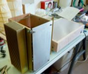
More F5 Images
That's a nice looking build. I wonder if the box with the heatsinks on it would benefit from more holes in the base to allow air to flow up inside it like a chimney.
Hi friends,
I am looking for the MATCHED pairs of Fet (in order to save time, even if I would prefer to buy the PCB from DIYaudio store), and I have found on the Hifi4sale forum (where a lot of people also build the F5) that this vendor "tubeshunter" provides such matched pairs:
DELUXE F5 STEREO FET & MOSFET AUDIO POWER AMPLIFIER KIT | eBay
Do you know if it is a trustable vendor ?
If not, do you have a source for these MATCHED pairs of Fets?
Thanks very much !
N
I bought my F5 kits from this forum member,
Tech DIY Company Store
and the PCB's from the forum store.
I'm currently selling matched pairs of iRFP244's. See my post on Aleph 4 Strictly DIY build for heatsink details.
Hi Andy,
I find your reply too later : I have already ordered the transistors, but I will contact you if there is a pb ...
Thanks very much !
I find your reply too later : I have already ordered the transistors, but I will contact you if there is a pb ...
Thanks very much !
As big as you can manage.
😎
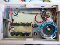
I finally managed to test-run my F5-in-StratosChassis yesterday. It's a basic version F5 with single pair of output FETs, 400VA Antek toroid, 120,000 uF PSU caps, etc. I just did not have access to machine shop so I decided to use the chassis of Odyssey Stratos. Stratos has massive heatsink while it barely gets warm, so I put the Stratos electronics in a small chassis with smaller heatsinks. It runs as it was in the big house.
Now F5-in-Stratos runs warm after a few hours test. The adjustment process was easy. AND, it sounds fantastic!!!
I would like to thank Mr. Pass for sharing such a nice work of art with DIY community.
And I confirm Mr. Pass' suggestion that the bigger the heatsinks the cooler the F5 runs. 😉
Doug
- Home
- Amplifiers
- Pass Labs
- F5 power amplifier