I'm using 5x20mm 2.5A fuses (slow blow) for my F5. I just popped one with my transformer and bridges hooked up into the power supply unit.
I tested each primary side of the transformer to the outputs of each bridge ok.
I might have a short somewhere in the power supply I guess.
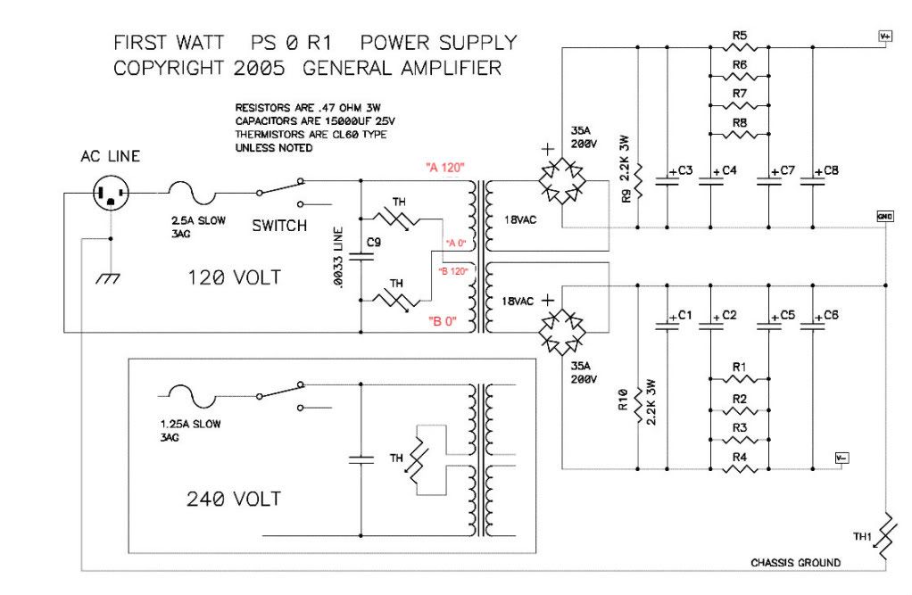
The most logical place to start is to make sure that you have each of the primaries connected properly, and then double check that the secondaries are also connected proper.
You should have continuity between the each black and red primaries, and the same on the green/blue secondaries. If you have any wire mis-connected, it will screw up half of the transformer, and pop the fuse.
Photos of your build would be very helpful to assist in troubleshooting.
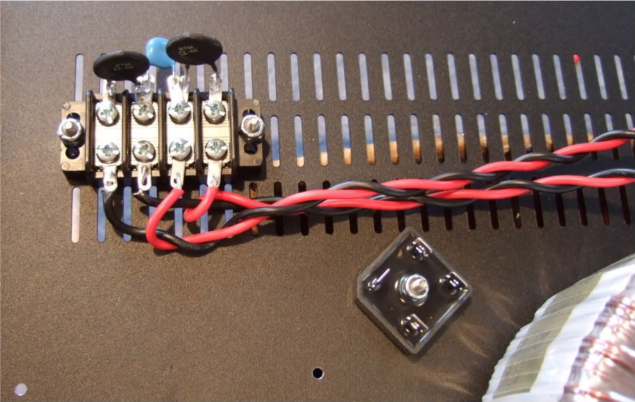
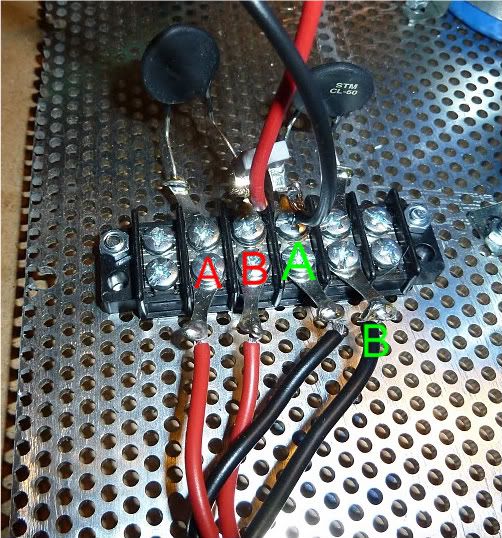
Here are some pictures of the connections in various builds -
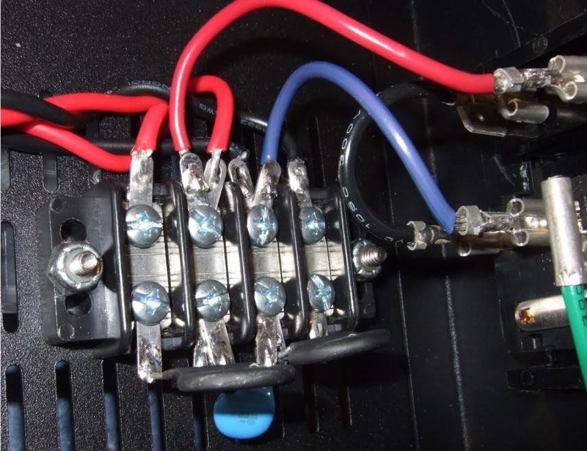
An externally hosted image should be here but it was not working when we last tested it.
Note the 'A' and 'B' primaries are the twisted pairs.
An externally hosted image should be here but it was not working when we last tested it.
An externally hosted image should be here but it was not working when we last tested it.
F5 finished
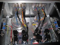
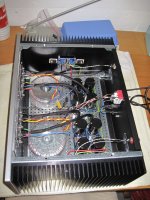
I finished my F5 today and it is working properly. Adjusted now at 90% of target Iqs for a few days to come and than I will test it again. Sound is already great. I am a happy man!! Thanks Peter Daniel for your pcb's and all your advices, h_a for the matched transistors, Zen Mod's very practical initial testing manual an of course mister Pass for giving us the scheme. Enjoying time started. Here are a few pics. 🙂
I finished my F5 today and it is working properly. Adjusted now at 90% of target Iqs for a few days to come and than I will test it again. Sound is already great. I am a happy man!! Thanks Peter Daniel for your pcb's and all your advices, h_a for the matched transistors, Zen Mod's very practical initial testing manual an of course mister Pass for giving us the scheme. Enjoying time started. Here are a few pics. 🙂
Attachments

Who summons the JFET genie?

Can I call the MOSFET genie about cascoding outputs of an F5?
not Mosfet Genie itself but resident Court Jester 
you don't need cascoding outputs on F5
just keep each one in safe area regardng dissipation and - if you need more overall dissipation - double number of outputs
they're more than capable , voltage vise
possible benefits from cascoding are smaller than harm induced by voltage losses
you don't need cascoding outputs on F5
just keep each one in safe area regardng dissipation and - if you need more overall dissipation - double number of outputs
they're more than capable , voltage vise
possible benefits from cascoding are smaller than harm induced by voltage losses
not Mosfet Genie itself but resident Court Jester
you don't need cascoding outputs on F5
just keep each one in safe area regarding dissipation and - if you need more overall dissipation - double number of outputs
they're more than capable , voltage vise
possible benefits from cascoding are smaller than harm induced by voltage losses
You may not have seen my earlier post, I want to use Toshiba 2SK3497/2SJ618 at least in single, and perhaps as multiple outputs. They have a high Ciss. I'd like to cascode in any case. I haven't seen much if anything about cascoding F5 outputs. I could be going down the wrong path, but it seems like cascoding might help in this case.
Do you have any thoughts on cascoding the output Mosfets on the F5, it opens up a lot of possibilities.
The top row red/black wires look to be a half mm from shorting in that picture.
......
Do you have any thoughts on cascoding the output Mosfets on the F5, it opens up a lot of possibilities.
patent 5343166
fig. 5
use PAT2PDF - Free PDF copies of patents: Download and print!
set cascode to have at least 15V across each gain mosfet
edit - disregard additional current sources across gain mosfets on Fig.5
Last edited:
Yes, cascoding could probably provide the best sound with the transistors your speaking of. The downside is going to be when you figure out how much heat sink and power supply you'll need and how little the power output is. you'll need something like twice the rail voltage. That probably will be twice the power dissapation to get the same output power as a pair of IRFs or Faichilds. They probably work better at higher voltage too!
It's not usually done for those reasons. Having said that, I would say your biggest bang for the buck, is higher bias with more heat sink.
It's not usually done for those reasons. Having said that, I would say your biggest bang for the buck, is higher bias with more heat sink.
Yes, cascoding could probably provide the best sound with the transistors your speaking of. The downside is going to be when you figure out how much heat sink and power supply you'll need and how little the power output is. you'll need something like twice the rail voltage. That probably will be twice the power dissapation to get the same output power as a pair of IRFs or Faichilds. They probably work better at higher voltage too!
It's not usually done for those reasons. Having said that, I would say your biggest bang for the buck, is higher bias with more heat sink.
I guess I'll try them as a drop in replacement to the 2SK1530/2SJ201s and see what happens.
Ya know, I havent really even looked at the data sheet and I should have or you'ld have reason to respond with more why's and where'for's... trying them for a drop in replacement might not be the ticket either?
The capacitance thing is important. So let's see 😱 Are these EUVL's choice for a reg xister on the F5-X? I didn't get to involvled there. My choice typially would be FQA28N15 I think. For a cascode too. Maybe not a cascode for that toshiba? I don't think I have a compliment so that might be moot?
There are alot of parameters that may or may not mean you have a good xistor for audio. Listening and taking Papa's EUVL and ZM's advice will get you there sooner.
I don't think I have a compliment so that might be moot?
how about this one ?
http://media.digikey.com/pdf/Data Sheets/Fairchild PDFs/FQA17P10.pdf
I would think I want to match Vgsth and transconductance first. Then maybe the Cs. The C curves don't all look the same shape either. Probably something higher current than the FQA17P10. Might be good to have Rthj in a similar area. Just my 2 cents though 
Last edited:
While here help pretty please
Opinions on FQP19N20C
This is TO 220
I would really appreciate same advice.
Is same spec as FQA19N20C?
What sort of watt out of it compared to each other?
Tanks
http://www.diyaudio.com/forums/swap-meet/182480-holco-mfr-15ppm-2w-sale.html
Opinions on FQP19N20C
This is TO 220
I would really appreciate same advice.
Is same spec as FQA19N20C?
What sort of watt out of it compared to each other?
Tanks
http://www.diyaudio.com/forums/swap-meet/182480-holco-mfr-15ppm-2w-sale.html
Last edited:
Nelson - the simplified schematic looks like a FET-ized version of the Universal Tiger output stage:
http://www.diyaudio.com/forums/solid-state/41926-universal-tiger.html
No offense, not that there is any connection.
How close will the output get to the rails? The voltage gain probably helps in this regard.
What outputs were used in the prototype if you don't mind my asking?
Is there a .pdf for the full design somewhere on the net ... Edit: found it here:
http://www.firstwatt.com/pdf/prod_f5_man.pdf
Last edited:
I finished my F5 today and it is working properly. Adjusted now at 90% of target Iqs for a few days to come and than I will test it again. Sound is already great. I am a happy man!! Thanks Peter Daniel for your pcb's and all your advices, h_a for the matched transistors, Zen Mod's very practical initial testing manual an of course mister Pass for giving us the scheme. Enjoying time started. Here are a few pics. 🙂
great looking amp
Hifi2000 case ? Is It 4U 300 - you got right amount of space for a dual mono
I see that you use Amplimo toroids - what are their spec - what Is your bias, any hum from toroids
regards
Recontinued my journey for dual output F5
I decided that now since the F4 was done I would go back to the F5 and try the double outputs again.
I went and ordered 4 pairs of 2sk1530 and 2sj201. I also took this opportunity to dust off the briangt psu board since I had to cannibalize the Peter D universal psu board for the f4 due to space constraints.
I stuffed the psu with 2X3X39000uf panasonic TUP caps. Then removed the irf mosfets and replaced them with the toshibas - also added the extra pair to the sinks and p2p'd them into the circuit. Biased to 470mV per fet and dialed in the dc offset.
Played it hard for about an hour tonight and all was well!!!
If my blown 2sk170 in the right channel stays away then I guess I will have to attribute my past issue with this to the irf fets...
How close will the output get to the rails?
A couple of volts. The losses are across the Source resistors and the saturation
voltage of the Mosfets.
😎
- Home
- Amplifiers
- Pass Labs
- F5 power amplifier