Re: Re: re: f5 PCB
I'll print it into Photoshop CS2, and do a PDF at 100%, but you'll probably have to get rid of the jaggy's from going to BMP. I'll post a PDF here.juma said:
Read my mail again 😉
It's 9.9 cm x 3.5 cm (1" = 2,54 cm)
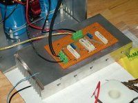
One dead bug channel of F5 is up and running.
Not having the correct devices on hand, I had to use some old junk-fets I had laying around, in this case a 2n4416A and a 2n5116. They had Idss's of 9ma and 12ma, closest match to the recommended I had on hand.
A 10khz square wave shows no overshoot, and looks very square.
Yes, that is speaker wire you see attached. After letting it warm up for about 40 minutes, it seemed very stable, so I hooked it up to a speaker and listened to one channel of Dido.
First impression was that the F5 does an amazing job of reproducing every aspect of her voice -- which is simply amazing.
Very detailed amp-I can't wait to do the other channel. (even though it is surely nowhere near one built with the right j-fets)
JJ
Attachments
Too late to take a picture, and I want to sit down with the XYL and watch some TV (it's almost 11 p.m. here in the People's Republic of New Jersey), but using separate gate input resistors has had a most salutory effect.
jupiterjune said:Not having the correct devices on hand, I had to use some old junk-fets I had laying around, in this case a 2n4416A and a 2n5116. They had Idss's of 9ma and 12ma, closest match to the recommended I had on hand.
A 10khz square wave shows no overshoot, and looks very square.
...(even though it is surely nowhere near one built with the right j-fets)
That the ticket. I'm sure that those JFETs work fine although they
do look to have a lower transconductance than the 2SK170/2SJ74.
While your article describes the basic circuit brilliantly in layman terms, it contains little details on how it is designed for stability given the high bandwidth. After so many informative articles on the Zen series plus other First Watt designs, perhaps you could shred some light on how you go about designing for frequency related performances ?? And I guess F5 would make a great example for that purpose, specially in the light of the difference in peformance as measured by jackinnj than your own .....
Looking forward to your enlightenment,
Patrick
Looking forward to your enlightenment,
Patrick
EUVL said:And I guess F5 would make a great example for that purpose, specially in the light of the difference in peformance as measured by jackinnj than your own .....
Why don't we start with his results?
> Why don't we start with his results?
Sure.
To achieve decent square waves at 100kHz as shown in your article, one would guess that one might want to get the closed loop bandwidth at something like 1MHz plus. As he showed in his measurements, the frontend, with its low impedance gate and source impedances, would probably have a corner frequency beyond that. Thus, it is probable that the first RC dip in open loop comes from the 600 ohm drain resistor and the input capacitance of the MOSFET. If this is far enough apart from the corner frequency of the input stage, then we should not get 180 deg phase shift when closing the loop. Correct ? One would guess that f1/f2 wants to be larger than the amount of negative feedback (say > 35dB).
However, the F5 is essentially two amplifiers mirrored about ground, and the frequency response of each half is different. So I guess this explains why there are more than 1 peak in the frequency response. I have not worked out all the RC values yet (if I remember correctly, the MOSFET gate has a corner frequency of something like 30-40 kHz), but assuming the same devices, I wonder why he is getting such different response than you did ??
Patrick
EUVL said:> ...why he is getting such different response than you did ??
It happens when people worry too much. Your emotional energy radiates the field that modifies reality in accordance with strength and type of your emotions. It's a fact well known by anyone in quest for enlightenment.

juma said:
It happens when people worry too much. Your emotional energy radiates the field that modifies reality in accordance with strength and type of your emotions. It's a fact well known by anyone in quest for enlightenment.

you're barking up wrong tree this time ........

Change of Jfet
Dear all,
What should I notice with the Data Sheet, if I want to change the Jfet ?
I have many K240/J75 and K147/J72 on hand !
Thanks !
Dear all,
What should I notice with the Data Sheet, if I want to change the Jfet ?
I have many K240/J75 and K147/J72 on hand !
Thanks !
Enlightenment :
A philosophical movement of the 18th century that emphasized the use of reason to scrutinize previously accepted doctrines and traditions and that brought about many humanitarian reforms.
Now can we get back to designing for bandwidth ?
Patrick
A philosophical movement of the 18th century that emphasized the use of reason to scrutinize previously accepted doctrines and traditions and that brought about many humanitarian reforms.
Now can we get back to designing for bandwidth ?
Patrick
Re: Change of Jfet
Since you have them, I would plug them in and see what you get.
thomasfw said:What should I notice with the Data Sheet, if I want to change the
Jfet ? I have many K240/J75 and K147/J72 on hand !
Since you have them, I would plug them in and see what you get.
EUVL said:Now can we get back to designing for bandwidth ?
Is that what we're trying to do? I didn't design for bandwidth on this,
I just failed to limit the bandwidth that occurred.
😎
I do not expect that you choose your resistor values and bias values by chance, right ?
Patrick
Patrick
supernet said:Did anyone else also had problems downloading F5 article from firstwatt webpage?😕
If your talking about the owners manual then yes. I think there is a problem.
My personal feeling is that Nelson is still trying to get us to figure out the PS differences from the unregulated F4, if any, or how to sneak a few more volts in. The sixmoons article looked to be the same.

EUVL said:I do not expect that you choose your resistor values and bias values by chance, right ?
Patrick
Patrick -- PM me --
- Home
- Amplifiers
- Pass Labs
- F5 power amplifier