Well, grounding scheme suggested by tinitus looks like a good idea,...
That grounding scheme is fine for monoblocks, but ground-loop induced crosstalk becomes a problem with a pair of channels sharing a single power supply. I have done some SPICE simulations of alternative F5 grounding schemes when ground wiring topology, resistance, and inductance is considered. The main issue regarding grounding in a stereo-channel F5 is the non-trivial amount of AC current in the feedback path thru R5||R7 and R1, and the ground loop created by the ground-returns of the 2 inputs.
I will distill my SPICE simulations down to something simple that illustrates this in a future submission.
The point of the discussion was to come to agreement where the star ground should be.
Should it be on the pcb? Should it be at the -ve speaker binding post? Should it be at the power supply 0V? or Should it be at a remote location as discussed by Andrew and drawn by tinitus.
My next questions is how do do this? Do you guys use a terminal block as the star ground or what other ideas do you guys have.
Once we are in total agreement on how to do this, then we can talk about the differnce between monoblock and stereo configuration.
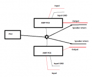
Hi Tinitus sorry if I am stretching the friendship. It would be nice if you labeled your diagram (eg Input Sig gnd, Output gnd, PCB, Power supply, star etc) and reposted it for everyone. I know it is obvious for most people but it would be good to do this for completeness.
Should it be on the pcb? Should it be at the -ve speaker binding post? Should it be at the power supply 0V? or Should it be at a remote location as discussed by Andrew and drawn by tinitus.
My next questions is how do do this? Do you guys use a terminal block as the star ground or what other ideas do you guys have.
Once we are in total agreement on how to do this, then we can talk about the differnce between monoblock and stereo configuration.
Hi Tinitus sorry if I am stretching the friendship. It would be nice if you labeled your diagram (eg Input Sig gnd, Output gnd, PCB, Power supply, star etc) and reposted it for everyone. I know it is obvious for most people but it would be good to do this for completeness.
I used the psu as "star"gnd.
And it is 100% silent, (and remarkably powerful with this psu...)
You can see that speaker-gnd is connected to the psu-gnd.
Arne K
I would do almost the same thing, but with all grounds going to a common star ground point somewhere else, including connecting the PSU ground to that star ground point.
But now theres talk about that configuration creating ground loops in a stereo amplifier.😱
Hi
I'm reading this with interest as I still have a slight hum with my stereo F5. It doesn't bother me that much, but I plan to rewire the amp at some point and it will be nice to try the 'preferred' ground layout
Happy new year to all! 🙂
I'm reading this with interest as I still have a slight hum with my stereo F5. It doesn't bother me that much, but I plan to rewire the amp at some point and it will be nice to try the 'preferred' ground layout
Happy new year to all! 🙂
The Daniels power supply boards have the star ground located on the jumper for the grounds of the 2 halves of the power supply. Negative speaker output also comes from that point. Dead silent.
Russellc
Russellc
My 2 pence
Ground connections on the F5 are :
suply cord 1 earth cable
comon of the capacitors bank
ground connection of R10
ground connection of R1 /R2 and speakers return
4 wires maybe as R10 and R1/R2 at same point on PCB
There may be a loop between the pre amplifier ground on the power cord and the screen on the patch cables as tose are comonly terminated on both sides
May be worth looking at / cutting the connection on the patch cables between the pre amp and the F5 on the F5 side as pre and F5 are already connected to ground by the power cord
Attachments
Sorry posting at same time as RussellC
He is quite right as ref3 and ref4 on the star ground are at same point on Daniels boards
so Just 3 connection to star ground
He is quite right as ref3 and ref4 on the star ground are at same point on Daniels boards
so Just 3 connection to star ground
In case of a not cascoded F5, with multiples outputs Mosfets pairs
Why to use many output devices if not for increasing rail's voltage ?
This is the grounding scheme I'm going to use.
Seems from what I have read at various places something like this should be good to use.
There theoretically might be some crosstalk betweem channels due to the common ground for both of them, but really, is it such a big difference in real world applications?
Aa long as it doesnt have any audible effect in real world applications, shouldnt we strive to keep it as simple as possible?
Attachments
Last edited:
First power-on with one channel connected to the (shared) psu today.
Cviller boards, 18Vac tooroid, CLC filter, heatsinks from and old accurus amp (have no data on the sinks, they are probably a bit on the marginal side)
With 23Vdc from psu, 0,556V over the 0,47E resistors and from 0 to 2-3mV dc between out and psu-common/ground I got with my infrared termometer:
70C pointing at the mosfet (downside).
55C at the aluminum close to the mosfets
45C at the aluminum far away from the mosfets
45C at the screw/ washer mounting the mosfets
I think that increasing the bias is not at option. Don`t want the sinks any hotter on the outside. The sink were placed flat on a table and might have better airflow when mounted and lifted up a cm or two, but that will problably not matter much. When I put the lid on the box it willl also restirct airflow around the modules a bit. Guess BIG/many holes in the lid is a good thing.
Before I go any further I would like to hear comments on my results. Do you think I need to back off the bias some more?
No - I wouldn't think so. What was the temp in the room at the time? If it was roughly 20 degC then you had a rise of 25 degC - not too much. When the heatsinks get to 55 degC its time to stop!
The other thing is that having the heatsinks the right way will make quite a difference - also having good air circulation will also help. Theres quite a difference between the amp being on the top shelf and the middle shelf of the rack.
*********************************
Today I opened up my F5 - I had about 40-50mV bias on the outputs. Turns out that I was getting significantly different readings over the 0.47R resistors. Anyway, when I took one out at measured it I was getting 1.2R (although this has to be fairly approximate since most DMMs aren't too good down at that low level). I replaced that resistor and readjusted the amp. All is well again!
Fran
I'm reading this with interest as I still have a slight hum with my stereo F5. It doesn't bother me that much, but I plan to rewire the amp at some point and it will be nice to try the 'preferred' ground layout
If you could humor me and try connecting the input grounds as shown and let me know if your hum stops. 😉
Attachments

Last edited:
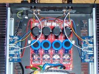
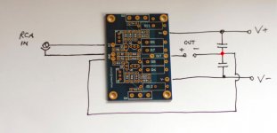
Try Peter Daniel's grounding approach, it works perfect. The red point is the PSU between the two main capacitors. Where you should connect your SPKR ground. Connect it too to the board.So correct grounding is basically annoying as hell, great.
Got to think about what Im going to do about it.
On board, the ground coming from the RCA is put there and joined to the PSU with a wire.
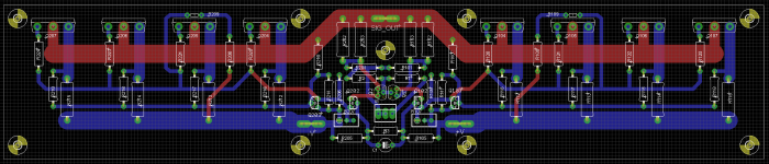
Attached are the grounding scheme plus boards layout. You can easily see how did he managed to arrange grounds. Zero noise or ground loops.
Attachments
Star ground crosstalk analysis
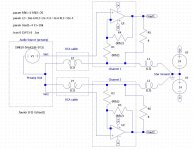
As promised, here are 3 SPICE circuits showing 3 different ground topologies for a stereo F5. The actual F5 amplifier circuits have been replaced by OP-amps to simplify the drawings. For the crosstalk analysis, only the AC signal currents, ground wiring inductances and resistances, and ground system noise voltages are important. In all tests, the assumptions were:
. 1 watt output from channel 1 into a 8 ohm load (4V p-p).
. 20KHz sine wave input to channel 1
. 0V input to channel 2
. 6 inches of #16 wire from PC board grounds to star ground point
. 36 inches of "typical" RCA cable interconnect cable.
In the 1st circuit (xtalk1.jpg) the speaker ground returns are routed thru each channel's PC board. This generates 35 mV crosstalk = -41db below 1 watt.
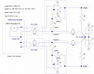
In the 2nd circuit (xtalk2.jpg) the speaker ground returns go directly to the star ground point. This generates 7.2mV crosstalk = -54db below 1 watt.
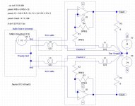
In the 3rd circuit (xtalk3.jpg) the input grounds go directly to the star ground point instead of the ground points of the PC boards. This has least crosstalk of 500pV = -198db below 1 watt.
In practice, acoustic crosstalk in a listening environment is likely to be HUGE in comparison to any of these values. So, why is interchannel crosstalk worth much attention?
As promised, here are 3 SPICE circuits showing 3 different ground topologies for a stereo F5. The actual F5 amplifier circuits have been replaced by OP-amps to simplify the drawings. For the crosstalk analysis, only the AC signal currents, ground wiring inductances and resistances, and ground system noise voltages are important. In all tests, the assumptions were:
. 1 watt output from channel 1 into a 8 ohm load (4V p-p).
. 20KHz sine wave input to channel 1
. 0V input to channel 2
. 6 inches of #16 wire from PC board grounds to star ground point
. 36 inches of "typical" RCA cable interconnect cable.
In the 1st circuit (xtalk1.jpg) the speaker ground returns are routed thru each channel's PC board. This generates 35 mV crosstalk = -41db below 1 watt.
In the 2nd circuit (xtalk2.jpg) the speaker ground returns go directly to the star ground point. This generates 7.2mV crosstalk = -54db below 1 watt.
In the 3rd circuit (xtalk3.jpg) the input grounds go directly to the star ground point instead of the ground points of the PC boards. This has least crosstalk of 500pV = -198db below 1 watt.
In practice, acoustic crosstalk in a listening environment is likely to be HUGE in comparison to any of these values. So, why is interchannel crosstalk worth much attention?
Attachments
Try Peter Daniel's grounding approach, it works perfect. The red point is the PSU between the two main capacitors. Where you should connect your SPKR ground. Connect it too to the board.
On board, the ground coming from the RCA is put there and joined to the PSU with a wire.
Attached are the grounding scheme plus boards layout. You can easily see how did he managed to arrange grounds. Zero noise or ground loops.
That is the way I normally do things but AndrewT reckons this way is not optimal and should be avoided.
You used a VERY tiny wire for speaker output, didn't you? I'm talking about the yellow one.I used the psu as "star"gnd.
And it is 100% silent, (and remarkably powerful with this psu...)
You can see that speaker-gnd is connected to the psu-gnd.
Arne K
Looking forward to see thatI've almost all the parts, and some of Peter's boards (bought 2 sets waaay back), stealth diodes etc, so I'm just waiting on some PS caps. This time I'm going to use an alu head from an engine for the chassis/heatsink.

- Home
- Amplifiers
- Pass Labs
- F5 power amplifier