Can you explain the difference in running a wire from psu 0v to star and making psu 0V star and running wires to it.
Either way they are connected to psu 0v.
I am definitely not arguing here, just trying to understand what the differnce is.
It would be nice if Nelson or someone could offer a diagram on how it should be done.
Either way they are connected to psu 0v.
I am definitely not arguing here, just trying to understand what the differnce is.
It would be nice if Nelson or someone could offer a diagram on how it should be done.
Well, what does Nelson do wrt grounding in F series of amps?
What he does should be good enough.
What he does should be good enough.
The pulsing currents that pass through the transformer secondary, on though the bridge rectifier into the smoothing caps and back to the secondary are not nice. They are large peak currents, they are spikey, they have RF on them, and any resonance created when the diodes switch off also run around this circuit.
Take a tapping from the Zero Volts.
Leave the far end of the tapping unconnected.
Connect a dummy load across the +ve and -ve supplies. What current is passing down the unterminated Zero Volts wire?
NONE.
Now instead, bring the main Audio Ground to the wire connecting the two smoothing caps. What is the current like through this wire?
Will all points along this wire be at the same voltage? Will any two points on this wire be at the same voltage?
Do not connect the Main Audio Ground on the Zero Volts line between the smoothing capacitors.
Now back to that unterminated wire from the Zero Volts connection.
Tie this into the amplifier.
The only output of the amplifier is it's own noise. That noise is the only signal passing back through the grounding wire to the Zero Volts on the PSU when the speaker/load is connected.
Now amplify a signal and send it out through the speaker connector.
It comes back through the speaker Return. That is an Audio Signal (and some distortion) only.
This Audio return current plus the amplifier noise is the only current that passes back through to the PSU Zero Volts. This wire connection from amplifier and speaker to PSU does not carry any of the noisy, spikey, RF and resonances that was flowing in the wire between the capacitors and around that rectifier secondary circuit.
Take a single wire from PSU to the Central Audio Ground and you isolate the rectifier charging circuit noise from the amplifier ground.
This slightly simplified, go and read
http://www.diyaudio.com/forums/diya...udio-component-grounding-interconnection.html
for the full story.
Last edited:
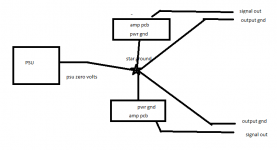
So if you make a single star ground point and connect the psu zero volts to that, then you can take both pcb power grounds and connect to that single point, as well as both output gnds should be taken from that single point.
Like attached picture.
Correct?
Like attached picture.
Correct?
Attachments
Last edited:
and the speaker returns and the signal grounds
Speaker returns is the same as output gnd, yes?
Or do you mean that the output gnds should go to the star point before they go to the output?
Signal gnds, you want the input signal ground to go to the star point as well?
The picture in my previous post should be ok?
with a star ground I wouldnt be needing out gnd on the pcb since I take that gnd connection from the star point?
Last edited:
Since all grounds are connected on the pcb anyway, wouldnt it be enough with just the pwr gnd connection going to the star point? Like the picture.
in reality there seems to be only one ground needed on the board, Jfet and signal ground
where to connect speaker ground I would say depends on the distance to your supply ground
I will have about 5 centimeter distance to supply
but some will have maybe like 20 centimeter, or more
I dont know, but then I guess it matters
if long distance, I would use the board ground spade connector (faston?)
not the board copper plane, but the spade connector itself
or you could place a star ground connector very close to the board, somehow

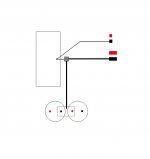
my ground scheme suggestion
HAPPY NEW YEAR TO ALL

Well, that looks quite alright. 🙂
Maybe Ill do it that way.
... but you can still parallel input Jfets if necessary.
Hi,
In case of a not cascoded F5, with multiples outputs Mosfets pairs, like Melon Head do, can we benefit from Parallel jfets inputs or use Jfets with higter Idss like V instead of BL ?
Thanks
If you have fans attached to the fins, a controller allows you to turn them to rotate slower in winter while keeping the same noise. If you want to go higher bias, you can turn them faster.I am accounting using the computer heatsinks we talked about.Very pretty, though i don't get the point of it.
Not the most useful thing in the world but by the price, not a bad idea.
Are you referring to worst stability or worse sound? Where are you basing your opinion about sounding worse?LDR's instead of trimmers - interesting idea , but certainly with worse result comparing to plain cermet trimpots
Regards,
Regi
I'm not basing my opinion 
LDR's are simply fragile , comparing to plain cermet trimpot - regarding power and temperature behavior ;
that's enough for me .
I had my share of examining LDR's behavior , and I simply don't like idea of driving output's gate capacitance with signal modulated across them .
as always - YMMAMV .
LDR's are simply fragile , comparing to plain cermet trimpot - regarding power and temperature behavior ;
that's enough for me .
I had my share of examining LDR's behavior , and I simply don't like idea of driving output's gate capacitance with signal modulated across them .
as always - YMMAMV .
Last edited:
Not the most useful thing in the world but by the price, not a bad idea.
Agreed.
Maybe handy for those without aircon, or houses that heat up a lot in the summer period. Controlling 5 fans seems a bit much
Hasn't NP gone to opto isolators for biasing the J2?
I'm not biasing my opinion
LDR's are simply fragile , comparing to plain cermet trimpot - regarding power and temperature behavior ;
that's enough for me .
I had my share of examining LDR's behavior , and I simply don't like idea of driving output's gate capacitance with signal modulated across them .
as always - YMMAMV .
Well, grounding scheme suggested by tinitus looks like a good idea, Think I'll just reduce the grounds on the pcb to an input signal/JFET ground and a ground line from there to the star point.
PSU 0 volts, PCB input signal/JFET ground, speaker ground returns, all should go to the same star point.
The potentially quite large return currents are then kept away from the amplifier PCB.
Problem solved I should think.🙂
PSU 0 volts, PCB input signal/JFET ground, speaker ground returns, all should go to the same star point.
The potentially quite large return currents are then kept away from the amplifier PCB.
Problem solved I should think.🙂
Last edited:
- Home
- Amplifiers
- Pass Labs
- F5 power amplifier