MK132's with "holes" in them (!!!)
I feel like an idiot and most likely I am.
Thanks nonetheless. I am using the MILLs also.
Thanks,
I feel like an idiot and most likely I am.
Thanks nonetheless. I am using the MILLs also.
Thanks,
Hi Peter I cant understand why my email tracks keeps playing up, apologies.
I am after another two boards of the F5 and 4 x power supply boards if you happen to have any around.
My Mosfets keep shorting and overheating and I am not sure as to the reason why. They are insulated from the cooling plate but the holding screw is not isolated any further. However the screw passes through the hole in the IRFP with no visible metal so I presume further insulation is not necessary there. The current limiter was not added to the circuit and grounding is as per your diagram. I use no load when testing the amplifier and only via a variac. I have burnt out about 6 mosfets so far. Any other ideas?? Perhaps the JFETS should be replaced at the same time as well??
Nonetheless one board is damaged with all the 'messing about' trying to sort the problem out.
That was a meesage: Delivery to the following recipients failed.
I'm out of PS boards, but F5 amp boards still available. Payment info in the first post.
You don't need to isolate screws. Did you use thermal paste, was heatsink surface properly smoothed out? Where the mosfets placed in proper places; one link to BOM had an error:
http://www.diyaudio.com/forums/showthread.php?postid=1794930#post1794930
This is correct BOM: http://www.diyaudio.com/forums/attachment.php?s=&postid=1797070&stamp=1239194429
The input FETS should be OK.
HI Peter ok tonight i got the first board going it was an insulation problem just the tiniest of nicks on the edge where the insulator pad had not fully covered. Repositioned the pad and first channel now works fine.Thank goodness for that I was getting quite frustrated. Still the victory is equally emotionally stimulating as the frustrations were.This is my second ever attempt at an amplifier build after the gainclone which i did manage to get right the very first time to my surprise and is still running without a single hiccup!!!
finished the amp with transformers in a separate case. very sweet sound yet also somewhat more energic than i'm use to, even with carbon hybrid VDH signal cabling internally. Voices sound supremely accurate and present to my ears, the tonality in the midrange is spot on and the bass is typical solid state.... deep and powerful.Needs to burn in and then tried out on my main system before making any further conclusions. Will play it against the gainclone.
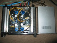
here is a shot of my set up using an old yamaha p series power amp chassis with heat sinks already built in. Four toroidal transformers sit in the case adjacent externally. As you might be able to make out one of the mosfets has been removed due to burn out I did not use paste!!! Worked for about an hour before burning out.
Attachments
using Pete's power supply boards simply takes the thinking out of getting it right is neat and smarter looking.
Hi Peter,
I am from Malaysia .
Would like to buy a set of the F5 boards for a stereo set.
Any more left ?
Thanks
kp93300
I am from Malaysia .
Would like to buy a set of the F5 boards for a stereo set.
Any more left ?
Thanks
kp93300
Hi Peter,
I have send the paypal payment.
Please use the shipping address as stated in the paypal message.
Thanks
kp93300
I have send the paypal payment.
Please use the shipping address as stated in the paypal message.
Thanks
kp93300
Peter, Paypal payment done. I have forgotten to add my town to the shipping address, oops!
Please append Den Haag after 2547BG. Thanks!
Bert K.
Please append Den Haag after 2547BG. Thanks!
Bert K.
Thanks Peter, great doing business with you. I will not build it any time soon however. I'm building a mini Aleph at the moment. Only ordered the F5 PCBs now while stock still lasts so I wouldn't be the one left without a chair when the music stops.
Peter, a question. Is your F5 layout based on using ZTX450/550 transistors or BC550/560 transistors?
Apparently ZTX's and BC's don't share the same pinouts.
Apparently ZTX's and BC's don't share the same pinouts.
My layout is based on original schematic published by Nelson Pass (with ZTX devices). Schematic is always supplied with the boards.
Peter Daniel said:My layout is based on original schematic published by Nelson Pass (with ZTX devices). Schematic is always supplied with the boards.
OK many thanks Peter. Very nice touch to include the schematic. Appreciated by many no doubt.
Cheers,
Bert
- Status
- Not open for further replies.
- Home
- Group Buys
- F5 pcb group buy...