Not much of a difirence between the big ones and the small ones then.
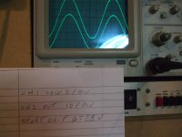
I just connected my amp up to my scope for the first time.
This amp does not have either the 10pf or 1nf caps suggested for stability and overshoot yet.
It seems pretty smooth sailing until it gets in the vicinity of the clipping voltage, then it rings like mad.
Square wave is problematic as I don't have the proper lead for my sig gen, just useing some lampcord. The signal and output overshoots, but the sqare looks ok if I test it at the output plug on the sig gen...
Anyway here is 26.895V into 8.2ohms (10W?)
Attachments
Hi Tea bag
Yes correct.
Hi Digits
No much difference between big ones and small ones.
No not at all maybe small FQP are closer to the P channel counterpart current wise.
At such small current (only 1.4 amps on each) I tok a reading at the Drain Pin next to the case of the mosfet (that is the closest point to the Junction where it all happens)
and got 56 C for both P and N channels (yes got new PT100 probe and is realy tiny 2.4 X1.2 mm) while the top of the heat spreader sit at 46C
I am going to give it a week before pushing more.
Sorry Digits don't get your W 26 X26 /8 = 80 od W
What Voltagge on the rails?
I pushed a sine to 20 V on 26V rails on 4 Homs and Papa mentioned that Clipping does not happen till you get to about 2 V from the rail.
Last edited:
Hi, my rails are a little under 15V, as I tried the PSU configuration I normally use in AB amps, it has a R and L parallel in between the two banks of C, total resistance for that bit is a little high (about 2 ohms). Gotta wait for more money to get the second set of nice caps then I'll play with just R or C in between, my wife wiped my finaces out last weekend. Its pretty good I think to swing that far on such low rails over 13V on each peak.
Do you know of a safe method of limiting the max input voltage to say 1.2V... that doesn;t mess up the sound quality?
Do you know of a safe method of limiting the max input voltage to say 1.2V... that doesn;t mess up the sound quality?
Last edited:
Hi Digits,
are the output current limiters fitted?
How close are the transistors to turn on? Is Vbe >=400mV?
are the output current limiters fitted?
How close are the transistors to turn on? Is Vbe >=400mV?
Which transistor andrew? one of the ztx jobbies?
what output current limiters, I just have the two .47R resistors on the output fets and the two 0.47R on the output.
Amp is biased to 1.25A
what output current limiters, I just have the two .47R resistors on the output fets and the two 0.47R on the output.
Amp is biased to 1.25A
This is worse than me trying to follow a cookbook.
Place the egg in a pan. Fill with water. Bring to a simmer. Where is the dictionary? Simmer = xyz. "bring to a simmer" ?? Where do I take it.
That's the level some of our Members are at, but they refuse to use the dictionary !!!
Place the egg in a pan. Fill with water. Bring to a simmer. Where is the dictionary? Simmer = xyz. "bring to a simmer" ?? Where do I take it.
That's the level some of our Members are at, but they refuse to use the dictionary !!!
I'm just confused as there are only 2 transistors, one protects against shorts on the output and the other one, well I'm not sure what it does 😛 (they are the ztx transistors).
I'm a total noob at useing a scope, very scared of probeing the wrong thing. Watch out for your cows.
I'm a total noob at useing a scope, very scared of probeing the wrong thing. Watch out for your cows.
Digits, that is parasitic oscillation.
Best to find the cause and fix it. Start with all the parts that NP suggests, then remove things you think might "help" the sound.
A Wayne - much has been written about the effects of the power resistors in the F5. Rick, I don't have amps built, has changed the resistors and ended up with Caddock's iirc on the outputs... Ymmv. I personally do not have any preferences to express at this point, but different resistors seem to impart some changes in the subjectively perceived sound... Rick does this stuff on his own, we talk, on occasion he brings the results over for a listen... fyi, and fwiw...
Simon published a study on resistors which can be found in the Blowtorch II discussion, and possibly in a search... bottom line is that as far as measurements go, use higher wattage, and possibly resistors in parallel to achieve that, unless you use something like a Caddock, etc... or so it seems.
_-_-bear
OK, appart from agravating thw one channel (probably some small mishap) the addition of the 10p cap and 1n caps in their suggested places seems to have cleared up the issue with that ringing on the sine wave. There is still a bit of overshoot with the square waves, which I suspect to be cable related to a large extent. On the sine waves I get a nice clean sine now, with clipping starting to set on as you just about reach 27V pk-pk into 8 ohms. Its a pretty square wave looking clip now with no ringing that jumps out and bites you from the scope screen.
I didn't get to do too much on the amp today, I did however rip the tiny (OLD) psu caps from my signal generator and swapped a bit more capacitance. Signals are much sharper now and it doesn't create the suprious blips inthe waves it did before. Also the square wave I can measure on it's output plug is now looking MUCH better than before I suspect I can improve quite a bit more as it hardly has decoupling caps for the opamps inside (lots of 471's) etc. but I don't have the distortion meter and frequency counter to calibrate it again should parameters change.
I saw where the transistor thingies is Andrew talked about, it would be a little hard to measure them at the moment, but I am makeing provision for them to have test points on the final boards.
Last edited:
Dear DIY´ers
I would like to build an F5, but since my speakers (Isophon Europa, impedance minimum 3Ohm) sensitivity is only about 86dB, i wonder wether this will be a good combination.
For the last two years i have been running a B1 and an A75, an absolutely fantastic combination. Thank you, Mr. Pass.
I do not expect the F5 to play anywhere as loud as the A75, but will it be a reasonable combination ?
Thanks for your thoughts,
Norbert
Bk - I think you missed a decimal point? Assumin ur digits are the right ones...
Norbert - consider the "X" version or other bridged versions? Up to 4x the power.
Much depends on your typical listening levels and the size of your room...
_-_-bear
Norbert - consider the "X" version or other bridged versions? Up to 4x the power.
Much depends on your typical listening levels and the size of your room...
_-_-bear
Maybe got my mat wrong or maybe I am talking different thing.
There is 56 V worth of swing and that is what a woofer wuld see (but not realy because all woofers are not perfect) so it will be -28V worth of movment inside the speaker and then + 28 volts worth outside the speaker those 56 volts worth of movment or work will push air bacward and forward causing a considerable amount off distress to neigbours and such and at the same time waves of low and higher pressure in the room .
Not particulary picking on you but as I did no mention Route Mean Square and to show you that I do understand your point and that I am also able to gogle things up
Have a quote from wikipedia
DefinitionOne watt is the rate at which work is done when an object's velocity is held constant at one meter per second against constant opposing force of one newton.
In terms of electromagnetism, one watt is the rate at which work is done when one ampere (A) of current flows through an electrical potential difference of one volt (V).
Two additional unit conversions for watt can be found using the above equation and Ohm's Law.
Where ohm (Ω) is the SI derived unit of electrical resistance.
Have a quote > about peak power as well
The dimension of power is energy divided by time. The unit of power is the watt (W), which is equal to one joule per second. Other units of power include ergs per second (erg/s), horsepower (hp), metric horsepower (Pferdestärke (PS) or cheval vapeur, CV), and foot-pounds per minute. One horsepower is equivalent to 33,000 foot-pounds per minute, or the power required to lift 550 pounds by one foot in one second, and is equivalent to about 746 watts. Other units include dBm, a relative logarithmic measure with 1 milliwatt as reference; (food) calories per hour (often referred to as kilocalories per hour); Btu per hour (Btu/h); and tons of refrigeration (12,000 Btu/h).
[edit] Mechanical powerIn mechanics, the work done on an object is related to the forces acting on it by
where
F is force
Δd is the displacement of the object.
This is often summarized by saying that work is equal to the force acting on an object times its displacement (how far the object moves while the force acts on it). Note that only motion that is along the same axis as the force "counts", however; a force in the same direction as motion produces positive work, and a force in an opposing direction of motion provides negative work, while motion perpendicular to the force yields zero work.
Differentiating by time gives that the instantaneous power is equal to the force times the object's velocity v(t):
.
The average power is then
.
This formula is important in characterizing engines—the power output of an engine is equal to the force it exerts multiplied by its velocity.
In rotational systems, power is related to the torque (τ) and angular velocity (ω):
.
Or
The average power is therefore
.
In systems with fluid flow, power is related to pressure, p and volumetric flow rate, Q:
where
p is pressure (in pascals, or N/m2 in SI units)
Q is volumetric flow rate (in m3/s in SI units)
[edit] Electrical powerMain article: Electric power
[edit] Instantaneous electrical powerThe instantaneous electrical power P delivered to a component is given by
where
P(t) is the instantaneous power, measured in watts (joules per second)
V(t) is the potential difference (or voltage drop) across the component, measured in volts
I(t) is the current through it, measured in amperes
If the component is a resistor with time-invariant voltage to current ratio, then:
where
is the resistance, measured in ohms.
[edit] Peak power and duty cycle
In a train of identical pulses, the instantaneous power is a periodic function of time. The ratio of the pulse duration to the period is equal to the ratio of the average power to the peak power. It is also called the duty cycle (see text for definitions).In the case of a periodic signal s(t) of period T, like a train of identical pulses, the instantaneous power p(t) = | s(t) | 2 is also a periodic function of period T. The peak power is simply defined by:
P0 = max[p(t)].
The peak power is not always readily measurable, however, and the measurement of the average power Pavg is more commonly performed by an instrument. If one defines the energy per pulse as:
then the average power is:
.
One may define the pulse length τ such that P0τ = εpulse so that the ratios
are equal. These ratios are called the duty cycle of the pulse train.
Is all in wikipedia nothing clever there
Peak power is the maximum level of work or energy output that is measured during an observation period. See also: Power-Physics Exercise physiologists measure peak power in their evaluation of human energy-generating capacities. Peak power also refers to the time of day when there is the most demand for electricity, requiring more power from the electrical grid. Some plans for creating a more energy-efficient infrastructure call for power plants which are only online during peak times. Peak power here refers to the maximum amount of power an electronic component can possibly handle for an instant without damage. Because of the highly dynamic nature of many audio signals (eg, music, which accounts for an alternative name, music power) there is some sense in attempting to characterize the ability of equipment to handle quickly changing power levels. But, how small an instant is a matter of some variation from observer to observer and so a peak power rating is necessarily more than a little indeterminate.
It always produces a higher value than the continuous ("RMS") figure, however, and so has been tempting to use in advertising. Generally, whatever the definition of instant used, distortion is also higher for an instant. For instance, an amplifier (especially a surround sound receiver), may be rated at 1,000 watts peak power, but the harmonic distortion level might be 10 percent under those conditions. Peak power is also referred to as max power or PMPO (Peak Music Power Output).[1]
Peak power is a common way to rate the power handling electronics, especially loudspeakers and amplifiers. It is a very impractical and exaggerated rating used by manufacturers to make their products seem much more powerful than they actually are. Peak power refers to the maximum amount of power something can handle before damage. In speakers, the peak power rating (also referred to as "max power" or Peak Music Power Output (PMPO), is often five or six times greater than the continuous ("RMS") rating.[citation needed]
Ambiguity: Among amplifiers, the peak power rating is fairly ambiguous as it varies depending on "acceptable" maximum harmonic distortion.[citation needed] For example, the peak power output rating of surround sound receivers is often taken at 10 percent THD.[citation needed] The highest generally acceptable level of total harmonic distortion is considered to be 0.1%. Hence, two max power output ratings are sometimes provided, one at 0.1% THD, and another at 10% THD.[citation needed]
Last edited:
The thing is there are as many ways to calculate PMPO as there are shrewd manufacturers. Whereas the RMS rateing is a universaly standard method of determining true output. Power out can not be more than power in, therefor I find most PMPO rateings wishfull thinking with no relevance to to true output power.
Hi digits
You are absolutley right.
Just one post sometink meaning to say one amplifier will make loads of "noise" whitout burping so 52 volts swing on a 10 Homs load and end up having lesson on Homs law.
I not picking on Bear and my apolologies for that I was wound up by other post on other tread by same compulsive poster with avverage of 10.4 post a day on other tread.
I wonder why I bother same times
if you calculate peak-to-peak power then you are deluding yourself in some way.
Peak power is taken to be 1/2 peak to peak.
How much power are you drawing from the wall? Is it 300 watts?
Get back to me on this?
😀
_-_-bear
Peak power is taken to be 1/2 peak to peak.
How much power are you drawing from the wall? Is it 300 watts?
Get back to me on this?
😀
_-_-bear
Hi bear
No delusion at all as mentioned all I was looking at was 52 voltagge swing on the 10 Homs
resistor silly silly me to mention any sort of watt or such or even to do same maths.
Why is peack power only half the voltagge?
Power from wall would be meaningles and would be RMS as most of the juce would came out of the caps when the thing is plaiing music so all RMS calcs out of window as we are not talking sines anymore is it?
Troug power suply so trafos rectifiers caps and same r then caps again and same more R and a couple of chokes and same morecaps
It al warms up a bit and waste same energy and has a bit of impedence
so instantaneous power on musica be different thing as litle impedence between caps and mosfets and not a sine wave.
Any way I se the error of my way and concede that I should have never posted that 313number so my apolologies again as a penitence I will listen to same Cylla Black and Bon Iovy.
Why peack power is taken as only 1/2 peack to peack?
I realy don't know
- Home
- Amplifiers
- Pass Labs
- F5 Listening Impressions & Discussion