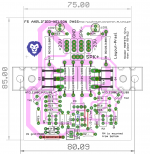
Wanted to make a layout for F5 as per fig 1 of http://www.firstwatt.com/pdf/art_f5_turbo.pdf for those who to want to etch their own pcb.
here it is. any comments on the layout welcome🙂.
the ground lift components (anti parallel diodes and resistor) are optional. LED and its resistor are also optional.
mosfet mounting hole center to center distance is 64mm.
Is it enough that the NTC touches the Heatsink?
reg
Prasi
here it is. any comments on the layout welcome🙂.
the ground lift components (anti parallel diodes and resistor) are optional. LED and its resistor are also optional.
mosfet mounting hole center to center distance is 64mm.
Is it enough that the NTC touches the Heatsink?
reg
Prasi
Attachments

Last edited:
The first thing I would do is to make it mountable on the UMS standard from diyaudio, this makes it easier for people with heatsinks drilled with the UMS patern.
The first thing I would do is to make it mountable on the UMS standard from diyaudio, this makes it easier for people with heatsinks drilled with the UMS patern.
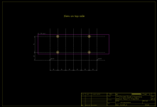
Thanks, I believe its possible to make the mounting distance as 80mm by moving both the MOSFETS by 8 mm in the above design.
The PCB will still be supported by MOSFET body like shown below.
hope you understand what i want to convey.
Attachments
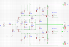
It's better to provide local supply decoupling with 16/18 mm capacitors (LS=5/7,5 mm) placed near the OPS and small-signal circuitry like this:

Prasi,
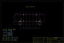
output MOSFETs are too close - put some distance between them to avoid creating a hot spot (each of them is dissipating almost 30W). Thermistor should be close to MOSFET so they can be in direct thermal contact.
No bypass caps are needed here, they can only cause instability.
It should look something like this (post #963 and #972):
http://www.diyaudio.com/forums/pass-labs/121228-f5-power-amplifier-20.html#post1525502
Last edited:
No bypass caps are needed here, they can only cause instability.
Are you really want to speak about stability?
🙂
F5 is an one-pole curcuit and it is inherently stable with it's simple feedback plot:

But, of course, each one-pole system can be used as output buffer and placed inside feedback loop of higher order system like this:

And there we can meet some instabilities...
Dear BesPav, I'm sure that simulation thrills you and it's good so. If you want it to really reflect the real life circuit you have to take into account all those small parasitic capacitaces and inductaces as well as non-ideal reactances that reality is made from. Otherwise, it's mostly stabbing in the dark.Are you really want to speak about stability?
I've built about a dozen of different F5 versions during the years and few times bypass caps did cause instabilities...
How do we explain the repeated reports of F5 blowing up after some weeks/months of successful operation?
How do we explain the repeated reports of F5 blowing up after some weeks/months of successful operation?
Well Andrew,
to be frank, I havent read about this amp too much , I came across the pdf link and I saw DIYA store PCB are available and thought to make a layout for the DIY PCB etchers.
Now I see that there is long thread on this amp as posted by Juma.
well for blowing up reports, life is a box of chocolates, you never know what you're gonna get!
I have a sneeky feeling (no more than that) it's the lack of supply rail decoupling that may be allowing intermittent oscillation and eventually causing semiconductor failure.If you want it to really reflect the real life circuit you have to take into account all those small parasitic capacitaces and inductaces as well as non-ideal reactances that reality is made from. Otherwise, it's mostly stabbing in the dark.
And I have almost 9 years old F5 built without rail decoupling caps that still performs flawlessly...I have a sneeky feeling...
Last edited:
It might even be the result of fakes being incorporated into the build.
The proportion of reported blow ups is quite small, but we still see a new report very occasionally.
The proportion of reported blow ups is quite small, but we still see a new report very occasionally.
I think it's rather about fake parts, low build quality and not understanding how the circuit works. F5 service manual is very good, everything is there and still members' posts show that only small number of builders read it.
Dear BesPav, I'm sure that simulation thrills you and it's good so.
Yea, it's very useful and really cheap way to easily find and resolve much of amps issues.
If you want it to really reflect the real life circuit you have to take into account all those small parasitic capacitaces and inductaces as well as non-ideal reactances that reality is made from.
Yup, in sensitive projects we have to perform extraction of S-parameters of planned layout with further schematic optimization.
Otherwise, it's mostly stabbing in the dark.
No, present models with audio applications up to ones of MHz are well corresponds to real amps:
http://www.amb.org/forum/simulating-beta24-t3213-10.html#p32648
Maybe we need to place in DIYA store some kind of hand-rectifier and amp-stabilizer for particularly outstanding and armless/brainless users?
😉
How do we explain the repeated reports of F5 blowing up after some weeks/months of successful operation?
The F5 sold very well, and after 9 years I still have not seen a failed unit.

Just how it should be Nelson with a properly engineered and manufactured product, sadly most product these days are built to accountants specifications - if you know what I mean.
main reason is either sheer inexperience of builder or most common reason from Yore Radio Amateur era - short circuit between headphones
- Home
- Amplifiers
- Pass Labs
- F5 layout