I have an issue with my F5 and pre-amp (well pot with buffer to be precise) combo and I can't make sense of it.
Warning: This is my first power amp and pre-amp, though I have built some headphone amp kits, so it could be quite obvious to you guys... Also, English is not my first language (having moved from continental Europe to the UK) so please excuse my lack of suitable vocabulary at times.
Laptop --> Audioquest Dragonfly --> F5: All good. Centred image (mono test track), no hum (by ear with my Tekton Lore Reference, 96dB 1W@1m claimed).
RaspberryPi w/ Allo Boss 1.2 DAC --> ACF 12Vac --> F5: Hum on both channels and image is slightly to the right (from listening position).
At first I thought it must be the pot or the pre, but there was no issue with the previous amp (Onkyo A-9010), nor with my Bottlehead Crack headphone amp. Hence the conclusion that it must be the "interaction" between pre and F5.
Following THIS presentation it sounds like a cross-channel ground loop. I tied the input grounds together at the chassis with a clamped on wire to try to solve it, but there was no noticeable effect. Not sure if the F5 has hum breaking resistors on the PCB... and how would that affect the channel balance / centre imaging? Maybe one side is oscillating?
The hum is not very loud, so I could live with it if I have to, but not with the off-centre imaging.
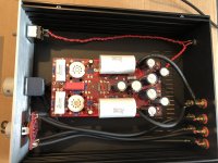
Please find some pictures attached. The case of the ACF 12Vac is connected to the star-ground on the PCB through a 3W resistor/cap under the board (so not visible).
Warning: This is my first power amp and pre-amp, though I have built some headphone amp kits, so it could be quite obvious to you guys... Also, English is not my first language (having moved from continental Europe to the UK) so please excuse my lack of suitable vocabulary at times.
Laptop --> Audioquest Dragonfly --> F5: All good. Centred image (mono test track), no hum (by ear with my Tekton Lore Reference, 96dB 1W@1m claimed).
RaspberryPi w/ Allo Boss 1.2 DAC --> ACF 12Vac --> F5: Hum on both channels and image is slightly to the right (from listening position).
At first I thought it must be the pot or the pre, but there was no issue with the previous amp (Onkyo A-9010), nor with my Bottlehead Crack headphone amp. Hence the conclusion that it must be the "interaction" between pre and F5.
Following THIS presentation it sounds like a cross-channel ground loop. I tied the input grounds together at the chassis with a clamped on wire to try to solve it, but there was no noticeable effect. Not sure if the F5 has hum breaking resistors on the PCB... and how would that affect the channel balance / centre imaging? Maybe one side is oscillating?
The hum is not very loud, so I could live with it if I have to, but not with the off-centre imaging.
Please find some pictures attached. The case of the ACF 12Vac is connected to the star-ground on the PCB through a 3W resistor/cap under the board (so not visible).
Attachments
To test for channel imbalance, compare the sound when swapping the audio cables at the input of the F5,
preferably using a mono recording. If the problem switches channels, the imbalance is before the amp.
Sort this out before looking into the hum problem.
preferably using a mono recording. If the problem switches channels, the imbalance is before the amp.
Sort this out before looking into the hum problem.
Last edited:
Nice tidy builds.
There's no hum-breaker on the F5 PCBs. Do you still get the hum if you place the pre-amp and power-amp back-to-back within a few inches of each other?
The power wires from your PSU board to your channel boards should be twisted, but I doubt that's the issue. (They could also use to be a bit heavier gauge -- same for wires between bridge rectifiers and PSU board.)
Cheers,
Jeff.
Sorry, forgot to mention, I switched the cables back and forth to no effect.
Thanks Jeff. The amps are next to each other. I tried putting them back-to-back as close as it gets with the cables (if I understand you correctly), but no change really.
The internal wiring (except LED wiring) is 16AWG. I'll try twisting them once I can find the time.
Thanks Jeff. The amps are next to each other. I tried putting them back-to-back as close as it gets with the cables (if I understand you correctly), but no change really.
The internal wiring (except LED wiring) is 16AWG. I'll try twisting them once I can find the time.
Hi Baobei,
16AWG is sufficient. (I've gotten used to silicone-insulated wiring which looks fatter because the insulation is thicker.)
With the two boxes back-to-back and the wiring you have, there's pretty much nothing inside the ground loop.
Is your tube-heater wiring twisted or on the preamp PCB? (I assume the heaters are DC given the single power entry into the preamp?)
Thanks Jeff,
The heater wiring is on the PCB (ACF 12Vac and Cathode-Coupled Amplifiers). And yes it's DC.
I tried some more things and the hum is only there when the pre-amp is on (and caps not empty). So I wonder if it is really a ground loop... Could it be my 12Vac wallwart? It's not the best, actually closer to 13Vac (I had to adjust the PSU resister to get the right voltages) and hums sometimes on its own....
Last edited:
"The ACF is basically the last half of the Aikido amplifier, a modified cathode follower buffer circuit that nulls the power-supply noise at its output by proactively injecting a small sample of the power-supply noise into the bottom triode's grid, which generates a countervailing current variation, which nulls the power-supply ripple from the output"
I'd look at how clean that +B is with an oscilloscope. Also, check if the heaters' DC has a ripple on it...
The RCA shields / outer jackets can be connected with a nice thick solid core copper wire, grounded at the star-ground on the PCB. But, do not go "around" and then feed the copper wire tail to the star ground; use a centre/midpoint from the connected RCA's wire (like "T connection")
That copper wire can be AC coupled to the chassis using something like 220nF polystyrene cap. Just make everything as short as possible (to minimise the impedance-to-ground at high frequencies)
Last edited:
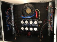
Ahh... I think Extreme_Boky is on the right track. Note that in your preamp the output coax cables form a loop around the rectifiers. I'd bet money that's where it's picking up the hum....
(To test this you could just bend one of the two outputs so that it follows the other: ie: there's nothing between them in the loop. But in the end you'll no doubt want to rewire the grounds as Exreme_Boky suggested.)
Cheers,
Jeff.
(To test this you could just bend one of the two outputs so that it follows the other: ie: there's nothing between them in the loop. But in the end you'll no doubt want to rewire the grounds as Exreme_Boky suggested.)
Cheers,
Jeff.
Hmm makes sense. Swapping tubes doesn't help.
The cables from the PCB to the output RCA plugs are too short to really move, but the right channel one is slightly longer, which could explain the channel imbalance (hum is louder on the right channel... possibly picking up more noise).
Just to clarify: If I do the rewire, do I take out the existing cables and replace without ground (which will go to the star ground on the bottom of the PCB)? I'm guessing I should keep the ground wire away from the AC input cables, correct?
Also, the chassis coupling: The chassis is currently connected to the star ground via a 3W resister in parallel with a small poly cap. Should I move that to the RCA plugs?
Sorry for the row of questions. This community is awesome!
Connection to chassis at star ground is fine.
Here's another simple test: cut the coax shield (ground) connection at one of the RCA plugs. Solder a wire from that RCA plug to the other one. You now only have a single ground going back from the RCA plugs, so no loop there. See if the hum goes away.
Here's another simple test: cut the coax shield (ground) connection at one of the RCA plugs. Solder a wire from that RCA plug to the other one. You now only have a single ground going back from the RCA plugs, so no loop there. See if the hum goes away.
I just desoldered the ground of one coax and connected the two RCA grounds. There is no change... 😕
I realised that if I switch the channel to something without a source (nothing plugged in) the hum gets louder / quieter when changing volume. With the RaspberryPi/Allo DAC plugged in the hum is constant. At the input grounds are all separate until reaching the PCB. Should they be tied together at input?
I realised that if I switch the channel to something without a source (nothing plugged in) the hum gets louder / quieter when changing volume. With the RaspberryPi/Allo DAC plugged in the hum is constant. At the input grounds are all separate until reaching the PCB. Should they be tied together at input?
All the input wires are fairly close together, so there's nothing in the loop. I doubt modifying the ground there will do anything. (Then again, I thought modifying it at the output would, so take that for what it's worth.)
BTW, the hum from an open input would be normal.
BTW, the hum from an open input would be normal.
Short the RCA input to RCA ground with a short piece of wire. Does it still hum? If YES, get the oscilloscope and check the power supply, as I mentioned before.
Can you tell if the hum is 100 Hz or 50 Hz? (or 120 Hz // 60 Hz, depending where in the world you are)
If 50/60 Hz --> Mains hum. Ground loop somewhere? Take a look at this: Rod Elliot P3A amp noises
If 100 / 120 Hz --> Could also be rectifier noise coming through the PSU.
If 50/60 Hz --> Mains hum. Ground loop somewhere? Take a look at this: Rod Elliot P3A amp noises
If 100 / 120 Hz --> Could also be rectifier noise coming through the PSU.
I think it's 100Hz. And yes it's still there when shorting the inputs to ground. However, it's only present when both channels are connected...
In any case, sounds like I need to go shopping for an oscilloscope. 🙂
If it is the PSU how would I fix it? Get a better transformer?
Thanks, learning loads here!
In any case, sounds like I need to go shopping for an oscilloscope. 🙂
If it is the PSU how would I fix it? Get a better transformer?
Thanks, learning loads here!
Quick update: I rewired the output of the preamp "just for fun". Still humming.
HOWEVER, I connected the right and left RCA on the F5 with an interconnect and the right channel clearly hums (even louder than with the preamp). The left channel is completely quiet. I used some wooden chopsticks to move around cables to see if there is any change. If I move the input coax the humming changes very slightly, whereas other cables don't have an influence if I move them... The input is quite far away from everything so I wonder what it could be.... bad solder joint?
EDIT: mbrennwa, thanks just read through https://www.updatemydynaco.com/documents/GroundingProblemsRev1p4.pdf. Where would a hum-breaking resistor go in a F5? All grounds on the PCB terminate in one "start ground" like point. Would in the input ground be the right spot?
Last edited:
I can't imagine a bad solder joint producing hum, but you never know.
Is the RCA jack seated in the middle of the hole in the back plate with a plastic washer on both sides (so that it makes no contact with the back plate)?
Is the RCA jack seated in the middle of the hole in the back plate with a plastic washer on both sides (so that it makes no contact with the back plate)?
Yes, they both are, just double checked.
I followed another tip from the hifisonix presentation and tied the RCA ground inlets together (two twisted 16awg wires just in case).
The hum is now lower volume and even on the left and right as far as I can tell. So at least the imaging seems fixed now (the right channel hum made it seem just that bit louder I think). So not entirely unhappy with the progress...
I have some speaker protection boards on the way (from the GB). When installing them I'll try twisting the power wires, let's see if that does anything. Another idea I had was getting rid of the ground wires from the input RCA's to the amp PCBs and solder a single one from the middle of the connecting wire between the RCAs (to create a "T" shape) to the PSU board "star ground". That would make the loop a lot smaller. Any harm in that?
(PS: Listening to a Chesky record and sounds pretty amazing already as is!)
- Home
- Amplifiers
- Pass Labs
- F5 "interaction" with pre-amp (hum, channel balance issue)