Actually EUVL's PDF calls for 1 watt source resistors:
http://xen-audio.com/documents/f5ha/F5-HA Description V1.4.pdf
But it also assumes 150ma of bias.
I also have the F5 power amp in my speaker system. Results have been similar. Stock bias is 1.6A. I am running 2.6A with 2 pairs of mosfets to distribute the heat and load. Reaction to increase in bias was expectedly similar, regardless of speaker load (class a envelope was enough even with low bias).
Sounds like a 1W resistor should be sufficient, you only dissipating no more than 200mw on each resistor. Is that correct?
That is correct. It depends on how comfortable you are running the source resistors hot. In general, you want to operate the resistor at less than half its rating, also...the ratings are usually at room temp in free air. So I would like the resistor to operate at 25% or less to be comfortable.
Higher bias will make a slight difference in authority.
The difference is more noticeable when you use a low impedance headphone, e.g. <50R.
For 300 ohm phones you are just wasting energy.
Dissipation is no problem for the FET and also not for the 2107 case if you use it properly.
The downside is a bit more DC drift.
But then we also have an optional DC servo for that. 🙂
And then you need to start increasing the PSU caps if you go higher than 200mA.
Else your ripple increases.
Unless you have an HE6 or K701, or any 16 ohm or 25 ohm planar, there is no need to go to 300mA, IMHO.
I use 2W resistors myself. They fit, and have no downside.
Patrick
Last edited:
Refer to post # 806.
I can confirm that the Beta tester has to give up the Beta test of the V2 PCB, for now.
Our hearts go to him and we wish him all the best and a full recovery soon.
In the meantime we have made alternative arrangement for the continuation of the Beta test.
We expect it to finish sometime around end of November, so that we can ship in time for Christmas.
Sorry for the delay.
But there are things in life much more important than DIY.
And I am sure you would understand.
Patrick
What do you think about LT3081/LT3091 followed by cap multiplier as PSU? Thinking about adding direct to the boards...
I have not tried. So go ahead and tell us afterwards.
The noise of the PSU is in the end determined by the CM, and unlikely by the regulator.
Subjective impressions are -- subjective.
Patrick
The noise of the PSU is in the end determined by the CM, and unlikely by the regulator.
Subjective impressions are -- subjective.
Patrick
Is there any theoretic reason why it would be better running positive + negative regulators (with cap multis), rather same setup but with postive + positive and make the center between supplies ground after regulator?
LT30x1 does have alot less dropout voltage than the LM's, and better regulation besides the lower noise.. Especially the smaller dropout is a big plus.
LT30x1 does have alot less dropout voltage than the LM's, and better regulation besides the lower noise.. Especially the smaller dropout is a big plus.
Last edited:
Depends on your transformer (CT or separate secondaries).
AND the Gnd (load) current has a shorter path, which is more important for SE than balanced.
Patrick
AND the Gnd (load) current has a shorter path, which is more important for SE than balanced.
Patrick
2N5457/60
I would like to try this amp, and I have "in stock" about 20 ea 2N5457 and 20 ea 2N5460. I'd like to use these in the initial build.
I found in a very early post (page 3, post #25) the attached schematic, using 2SK246/2SJ103. Full credit to EUVL, the original author, it is not mine.
Given that gm of 2N5457/60 is closer to gm of 2SK246/2SJ103 than LSK170/LSJ73, is this schematic a better choice for 2N5457/60? And if so, I think I'm shooting for about 1ma thru the jfet devices, correct?
I'm still trying to catch up, 800 posts is a lot of reading. If this has already been discussed a link (instead of a reply) would be most helpful.
Attachments
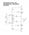
Sorry, but I cannot read anything on your graphics.
I have done no simulations with the devices you mentioned.
But I have posted the Spice files, so you can try to adapt that first.
Patrick
I have done no simulations with the devices you mentioned.
But I have posted the Spice files, so you can try to adapt that first.
Patrick
I think he was saying that the posted sch is that posted in post25.I found in a very early post (page 3, post #25) the attached schematic,
It looks the same with the very little detail available.
For low GM parts, that would be the schematics I would consider.
And I would choose a MOSFET with high Vgs at bias.
But it depends how you want to build.
If you want minimum distortion, there is no easy way round 2SK170/2SJ74.
The minimum you need is to match Idss & Yfs for the JFETs, and Vgs and Yfs for the MOSFETs.
In any case, I would still play with simulations first.
Patrick
I think he was saying that the posted sch is that posted in post25.
It looks the same with the very little detail available.
Yes, that is where I found the schematic, post 25. I did not realize the re-post was such low resolution, it was a quick cut-paste and I didn't check.
I am willing to accept that 2N5457/60 are less than ideal, but (1) I already have a number of those, and (2) this is an experiment to see if DC offset can be maintained within a reasonable level. I've not had good luck with other designs, but I suspect heat sinks too small. If I can get a reasonable offset then I'll be willing to buy the more expensive 2SK/2SJ devices.
The F5 manual shows FQP3P20/FQP3N30 have higher Vgs at bias than the IRF9610/610 parts.
You should use a low Idss pair of JFETs if you want to use the 5457/60.
Simulation shows 10x higher THD, mostly 2nd harmonics.
But then it is also only simulation.
Patrick
Simulation shows 10x higher THD, mostly 2nd harmonics.
But then it is also only simulation.
Patrick
D.L.Feucht discusses how to remove the output offset of a DC coupled jFET Buffer.Yes, that is where I found the schematic, post 25. I did not realize the re-post was such low resolution, it was a quick cut-paste and I didn't check.
I am willing to accept that 2N5457/60 are less than ideal, but (1) I already have a number of those, and (2) this is an experiment to see if DC offset can be maintained within a reasonable level. I've not had good luck with other designs, but I suspect heat sinks too small. If I can get a reasonable offset then I'll be willing to buy the more expensive 2SK/2SJ devices.
The F5 manual shows FQP3P20/FQP3N30 have higher Vgs at bias than the IRF9610/610 parts.
His arrangement is a Pass B1 with two extra resistors. One to adjust the current of the CCS/Lower device and one to adjust out the offset from the Vgs of the upper device.
Attachments
I guess he is worried about drift over time.
Offset can be easily trimmed with the JFET drain resistors.
Patrick
Offset can be easily trimmed with the JFET drain resistors.
Patrick
Are you looking for something like this? Still managed to fit within 100mm x 41mm. Not too sure about PSU and its caps values. I used a CRC type with 10mm dia caps. Some 2200uF 25V are available in 10mm dia. would they be sufficient? MURS are quite close to each other, may be one could use plastic packs or insulate their backs. A small C shaped aluminium plate could be used as a heatsink for the MURS.
reg
Prasi
Nice ! Caps must be larger or add cap multipliers or regs. Please no 78xx/79xx or 317/337 combo, those are old news. Preferably LDO low noise regs. X3 and X6 can be omitted.
Last edited:
Jean-paul: do you know of good low noise low dropout regs that would take higher input voltage then lt1963. I was thinking lt3081/lt3091 but would like to know if there is any better alternatives.
I think Patrick gave a hint a few posts back...
Not everything in Audio has to be powered by Salas or Super-regs... I learned this by trying other concepts.
The shunt regs failed badly trying to power my F5 HA, so eventually I tried a relatively simple cap multiplier
and the so-called Nazar reg with excellent results. Yes, they both have LM317/337 in them as pre-regs 😱,
but they do not determine the sonic performance here. Both sounded superb. As does the cap multiplier psu
in the DAO btw.
Of course you are free do do things much more complicated.
the noise of the PSU is in the end determined by the CM, and unlikely by the regulator.
Subjective impressions are -- subjective.
Not everything in Audio has to be powered by Salas or Super-regs... I learned this by trying other concepts.
The shunt regs failed badly trying to power my F5 HA, so eventually I tried a relatively simple cap multiplier
and the so-called Nazar reg with excellent results. Yes, they both have LM317/337 in them as pre-regs 😱,
but they do not determine the sonic performance here. Both sounded superb. As does the cap multiplier psu
in the DAO btw.
Of course you are free do do things much more complicated.
- Home
- Amplifiers
- Pass Labs
- F5 Headamp ?