I just placed an order from this seller. I plan to build this head-amp when I get back from vacation!
Steve
Hey....me too! As Spencer no longer has any left for sale I contacted Alweit after seeing his post...
http://www.diyaudio.com/forums/swap-meet/254307-some-2sj74bl-2sk170bl-2sj74gr-2sk170gr-matched.html
As 'BL' has been specified, this is what I have ordered.
The DAO has a lot more power and (shall I say) authority, but no gain.
Hi Patrick,
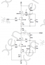
Can you please provide a link to the schematic for this DAO with no gain?
This sounds like something I may want to try.
Thanks...
BTW for those attempting the Vero build, don't use fancy super regulators to start with.
Simply CRC or lab supply would do.
A Salas shunt was tried with my prototype and ended up in oscillation.
In the end 27R power resistors were needed between amp and regulator to damp that out.
Once you got it working with a normal lab supply, as I did, you can then play around with other fancy things.
😉
Patrick
Yes, simple Aleph style regulator -> the Miles's C-Multiplier best match for the T-DAO - Slit Foil p/s o/p caps
I wonder how many here really understand what the differences are between all these "super regulators", & to the standard 3-pin ICs.
And why a lowly cap multiplier can be a better solution for certain applications.
Patrick
And why a lowly cap multiplier can be a better solution for certain applications.
Patrick
Dear Patrick,
Really want to know why, if you really kind to share.
what best application need cap multiplier?
i'm still on my office duty, once get back home. i build this amp, since i dont have decent headphone desktop amp.
best regards,
Really want to know why, if you really kind to share.
what best application need cap multiplier?
i'm still on my office duty, once get back home. i build this amp, since i dont have decent headphone desktop amp.
best regards,
This is a good read, as well as its pages 1 & 2.
Simple Voltage Regulators Part 2: Output Impedance
Note that at 150mA bias, the output impedance of a cap multiplier is about 0.2 ohm.
Patrick
Simple Voltage Regulators Part 2: Output Impedance
Note that at 150mA bias, the output impedance of a cap multiplier is about 0.2 ohm.
Patrick
May I ask where you got that heatsink?
As promised.
As I said, only a quick & dirty build to prove circuitry.
Took 5 hours from scratch to first sound.
🙂
Patrick
.
Don't you know our famous heatsinks ?
http://www.diyaudio.com/forums/solid-state/135154-next-best-thing-2sk389-2sj109.html
Patrick
I have space on the Vero board.
So I put two caps between Gnd and +Vs/-Vs.
As local as one can put it.
🙂
Don't you know our famous heatsinks ?
http://www.diyaudio.com/forums/solid-state/135154-next-best-thing-2sk389-2sj109.html
Patrick
The Caps is worth a try. I like the heatsink idea, one wouldn't even need a fancy C&C machine to make a rough version of those. Thanks.
The weekends here so I'm knocking up a temporary power supply whilst I wait for my jfets to arrive, hopefully next week. I will be using a simple capacitance multiplier. The demands of this circuit are very modest so it will probably be overkill but hey, I've got the bits lying around so why not.
I'm curious Patrick, I realize that you are using your lab supply for your prototype......now looking at your draft PCB layout, am I right in thinking you are going to use 3pin regs for your final build?
I'm curious Patrick, I realize that you are using your lab supply for your prototype......now looking at your draft PCB layout, am I right in thinking you are going to use 3pin regs for your final build?
Last edited:
I can see a couple of electros on your prototype photos, and there is room for them on the vero layout you provided, but they are not shown on the vero layout or the schematic. I presume they are just extra local filtering across the supply.......perhaps 1000uF (25v)?
Good guess. 1000µF 25V Panasonic FR, as I just have them handy.
You might probably get away with less, 330µF or so.
But if you feel like trying something interesting, I found this one a while ago :
S-Audio Systems - PSU for High end audio without electrolytic capacitors
Looks really interesting, but I have not had a chance to try.
The shunt transistor as posted has a current of 20mA at 15V, limited by its dissipation (set at 0.3W).
So you might want to use multiple ones in parallel, or change to a power transistor.
The shunt path should at least have half the max. output current you want to have to the headphone.
Assuming 8V 50 ohm, i.e. 160mA, you would want to have 4x in parallel.
And then as good stability practice put a small resistor (say 100R) at the base of each.
Patrick
- Home
- Amplifiers
- Pass Labs
- F5 Headamp ?