Ok I got it I think.
So, I can leave the two NTC's in place? Each PSU will have its own NTC connected to chassis at two different spots? Do these then need to be connected to star ground, or left only connected to chassis?
The Two NTCs can be bolted to any part of the chassis. They do not need to meet up with any of the other chassis connected wires.
So, I can leave the two NTC's in place? Each PSU will have its own NTC connected to chassis at two different spots? Do these then need to be connected to star ground, or left only connected to chassis?
This is Star Grounding.P.S Remove your black and blue wire between amp boards.
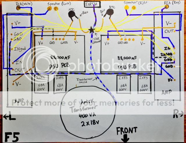

Those yellow wires are incorrect!
From RCA it's showing connection to earth ground. The simple solution is carry grounds like this -
From PS to amp board (for each channel)
From Speaker to amp board (for each channel)
From Isolated in RCA to amp board (for each channel)
From earth ground to chassis
From one PS board ground to another PS board ground.
From either PS (and through CL-60) to chassis bolt grounded to mains earth
From transformer shield to chassis grounded bolt, correct in diagram.
Additionally if you connect both RCA grounds together at RCA - RCA still it won't hurt.
The transformer shield MUST be connected to Chassis right beside where the shield comes out of the transformer using the shortest possible length of connector.
The NTC used as a Disconnecter between Main Audio Ground and Chassis may work adequately, since Pass recommends this. I have never seen a report on how effective the NTC is at passing Fault Current.
The PE should be connected to Chassis PERMANENTLY where it enters the Chassis. This connection should never be broken.

OK it seems there are different methods of going about this..
PE will be bolted to chassis using the method mentioned in Fig. 3 of the article mentioned above. Transformer shield will be connected to chassis with shortest wire possible.
AndrewT, do you agree with the most recent diagram from basi? With PE bolted to chassis then through CL-60 to the isolated star point?
There have been many ideas and i really appreciate it but it is hard for me to decipher which is the most effective.
PE will be bolted to chassis using the method mentioned in Fig. 3 of the article mentioned above. Transformer shield will be connected to chassis with shortest wire possible.
NO !!!!!
AndrewT, do you agree with the most recent diagram from basi? With PE bolted to chassis then through CL-60 to the isolated star point?
There have been many ideas and i really appreciate it but it is hard for me to decipher which is the most effective.
Basi' shows the PE going through the CL60 to the MAG.
If he meant different, then he needs to show different.
What he has shown is dangerous and potentially lethal.
If he meant different, then he needs to show different.
What he has shown is dangerous and potentially lethal.
Last edited:
I have been looking at the F5 thread (and others) for a couple of hours now. It seems that there are a lot of different ways to go about doing this..
Should I direct Signal Ground to Amp board via twisted pair, then Amp PCB GND to Main Audio Ground?? Or Sig ground (from RCA Jack) direct to MAG?
Main Audio Ground will be totally isolated from chassis (no contact) and connected through CL-60 to the Chassis Earth bolt..
Can I connect one PSU GND to the other PSU GND then connect them to Main Audio Ground through a single CL-60. Or is the CL-60 not required.
I am sorry for the confusion guys.. I am almost there, I promise
Earth (from the wall/IEC socket) will be bolted/soldered direct to chassis with 10 AWG wire. from this point there will be a CL-60 to the isolated MAG.
My question lie in the connections to MAG.
My question lie in the connections to MAG.
This problem does not come when you use 2 dual secondary transformer for 2 PS or single transformer with quad secondaries for 2 PS.
If you used only one dual transformer then you should have only one audio ground (MAG). Though you have 2 sets of PS (including its own rectifiers), still you have same ground referred at two output of PS. But this could lead minor difference at ground level of both PS output, thanks to tolerances of bridge rectifier diodes of both PS.
It would be get connected through input RCA ground of source or preamp, and conduct ground current proportional to difference of ground levels and ripple present. Thus evolve ground loop infringing input signal and amplified through amplifier. So get it corrected by connecting PS ground of both boards together near output of both PS boards, making single MAG.
From this central MAG all ground paths lead to Amp Board. RCA input ground ends on Amp board. Speaker ground terminates at Amp board or MAG star ground, does not matter.
^^This is correct.Earth (from the wall/IEC socket) will be bolted/soldered direct to chassis with 10 AWG wire. from this point there will be a CL-60 to the isolated MAG.
If you used only one dual transformer then you should have only one audio ground (MAG). Though you have 2 sets of PS (including its own rectifiers), still you have same ground referred at two output of PS. But this could lead minor difference at ground level of both PS output, thanks to tolerances of bridge rectifier diodes of both PS.
It would be get connected through input RCA ground of source or preamp, and conduct ground current proportional to difference of ground levels and ripple present. Thus evolve ground loop infringing input signal and amplified through amplifier. So get it corrected by connecting PS ground of both boards together near output of both PS boards, making single MAG.
From this central MAG all ground paths lead to Amp Board. RCA input ground ends on Amp board. Speaker ground terminates at Amp board or MAG star ground, does not matter.
Last edited:
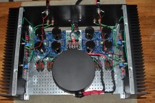
OK so I reconnected everything with a new grounding scheme. I think it might be a tiny bit quieter...
I checked bias and DC offset, everything is in good shape it seems.
The heatsinks are much much hotter to the touch... After ten minutes, the heatsinks were hotter than they had ever been. I will post photos tomorrow and show you guys how I did it.
Overall, I am a bit discouraged and frustrated. Oh yeah, and now there is a volume dependent hum when the squeezebox is turned off and the amp and preamp are plugged in only
Consider trying it with dual bridge feeding single PSU. If it kills the hum, you know you gotta either buy another transformer or a bigger psu to handle both sides. You could run your current dual block in series connection, doubling capacity
Consider trying it with dual bridge feeding single PSU.
I agree completely.
I know the dual PSU seems a bit dumb but they each have their own pair of bridge rectifiers. This is not the problem.
There is a ground loop between my F5 and my Transcendent Sound Grounded Grid Preamplifier. The grounded grid is stock, exactly as I built it from the kit.
When I take the grounded grid preamp out of the equation and feed direct from (Squeezebox Touch => Cambridge Audio DACmagic + => F5) the system is as quiet as a church mouse. Im talking silent! And with 103db sensitive hornspeakers.
The configuration of my F5 is not the problem (other than the ground scheme).
Could I add a ground loop breaker to my grounded grid? I think I am getting close to figuring this out..
Are the RCA jacks touching the chassis?
They are totally isolated, so are the speaker BP.
I don't believe you had previously mentioned that it was directly related to the preamp being in the chain.
haha, yeah that would have been quite helpful in helping me troubleshoot. I have just now removed the preamp from the chain so I didn't know. I never thought to do it... All the work I did on my ground scheme could have been avoided maybe.. But I had to open it up any way. I upgraded R9, R13, R14 to TX2575 resistors and had to change the orientation of the LED's on the amp boards.
Any ideas now that we have narrowed my problem down? I have been reading about ground loops in systems that use unbalanced interconnects.. I know why I am having the problem between my preamp and amp BUT i do not know the remedy.
Any ideas now that we have narrowed my problem down? I have been reading about ground loops in systems that use unbalanced interconnects.. I know why I am having the problem between my preamp and amp BUT i do not know the remedy.
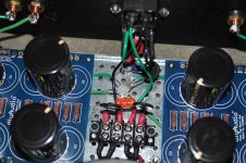
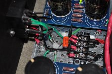
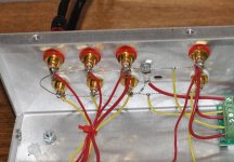
Ok here are some photos of my new isolated Main Audio (Star) Ground. It is isolated from chassis using nylon screw and nuts. All connections are in contact with each other, but are not in contact with the chassis. Main audio ground is connected to Chassis/Safety Earth via CL-60 thermistor.
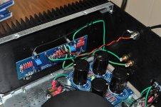
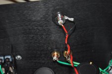
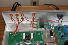
The last two photos are of my grounded grid preamplifier. There is a ground bus wire connecting all the RCA jack grounds. This ground bus is connected to Chassis/Safety Earth via a small 1/4 watt resistor.
The last two photos are of my grounded grid preamplifier. There is a ground bus wire connecting all the RCA jack grounds. This ground bus is connected to Chassis/Safety Earth via a small 1/4 watt resistor.
Attachments
- Status
- Not open for further replies.
- Home
- Amplifiers
- Pass Labs
- F5 Ground Loop - Need Ideas..