Hi, my F5 has a weird 60Hz hum that I cant cure.
Here's the situation.
With no inputs connected dead silent
With 1 input connected dead silent
With 2 inputs connected HUMMMMM
So is this a "cross channel" Ground Loop ?
So far I have tried a Hum Buster No Change
Lifted the ground via cheater plug No Change
Went from a non shielded i/c to a shielded i/c a little better but still not good
The amp is connected to a Battery Powered Preamp, don't know if that makes a difference ?
Could someone here give me some advice?
I have searched the F5 builder thread but didn't really see anything that would help
Attachments

Last edited:
View attachment 909280Thanks rayma !
Can you explain where the resistors go in more detail please.
My input cables are shielded but the shields are not connected to anything.
Do you mean the -ve input wire ?
Can you explain where the resistors go in more detail please.
My input cables are shielded but the shields are not connected to anything.
Do you mean the -ve input wire ?
Attachments
Last edited:
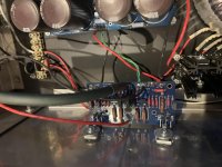
Yes, if you are using shielded twisted pair, instead insert the 10R in series with each "ground" lead
(instead of the shield). I'd guess that is the white wire? Use a separate resistor for each RCA,
even if only one resistor removes the hum.
The far end of the shield can remain connected where it is. The RCA end of the shield should remain unconnected.
(instead of the shield). I'd guess that is the white wire? Use a separate resistor for each RCA,
even if only one resistor removes the hum.
The far end of the shield can remain connected where it is. The RCA end of the shield should remain unconnected.
Last edited:
Use a separate resistor for each RCA,
even if only one resistor removes the hum.
I've wondered about this before, if one does the job isn't that better because you still have a low impedance return path?
Ok thanks I will try the resistors
It is a shielded twisted pair with the "shield" not connected at both ends.
I have always referred to the white wire as "signal return" or negative...
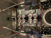
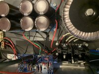
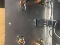
Transistors are isolated with paste and mica wafers
It is a shielded twisted pair with the "shield" not connected at both ends.
I have always referred to the white wire as "signal return" or negative...
Transistors are isolated with paste and mica wafers
I've wondered about this before, if one does the job isn't that better
because you still have a low impedance return path?
One may work sometimes, but it's system dependent and there's no reason to not use both.
Some amplifiers do use them as standard. Some don't need them, like monoblocks.
Depends on the layout, construction, and circuit, and DIY varies all over the map.
A stereo amplifier has an inherent susceptibility to ground loop hum.
Depends on the layout, construction, and circuit, and DIY varies all over the map.
A stereo amplifier has an inherent susceptibility to ground loop hum.
Last edited:
Should work if they don't touch the chassis, give it a try.
The value is not at all critical, 5R to 20R would be ok.
The value is not at all critical, 5R to 20R would be ok.
If this cures the hum, why isn't it standard on the build ?
Is there a trade off ?
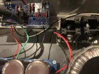
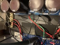
It sort of is standard. There is a "ground loop breaker" in the form of an NTC thermistor in the PSU schematic between the PSU (Audio GND) and chassis GND. I don't see that implemented in your build, but I may have missed it in the photos.
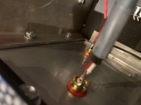
Separate topic / different thermistors - You should have your thermistors touching the body of the output devices (preferably) on the plastic body vs. hovering over your bolts. Contact, so they work to their best effect. On the body vs. the washer or bolt b/c if they fail and short to chassis ground, it may not end well. The latter part may be being a bit too on the edge of erring toward safety, but I've seen that practice referenced quite a bit. I used a different type of thermistor, so YMMV.
There's a better place to put the resistors, cross channel ground loop explained from page 4 https://www.updatemydynaco.com/documents/GroundingProblemsRev1p4.pdf
Interesting article , however I wouldn't know how to implement it on my F5.
I did put the 10r resistors at the rca jacks and it did help but did not totally remove the hum.
Is this not the "ground break" thermistor in the picture
I did put the 10r resistors at the rca jacks and it did help but did not totally remove the hum.
Is this not the "ground break" thermistor in the picture
Attachments
Last edited:
Matters a lot. You must have amplifier design and layout to the highest standards for such efficient speakers.
This is your best reference. Any differences should be viewed with suspicion.
Firstwatt F5 amplifier v3 - diyAudio Guides
This is your best reference. Any differences should be viewed with suspicion.
Firstwatt F5 amplifier v3 - diyAudio Guides
Last edited:
- Home
- Amplifiers
- Pass Labs
- F5 Ground Loop hum help please