Interesting article , however I wouldn't know how to implement it on my F5.
I did put the 10r resistors at the rca jacks and it did help but did not totally remove the hum.
Is this not the "ground break" thermistor in the picture
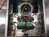
The two to the left in the photo with your cap on the mains / transformer primary terminal block are there for inrush current limiting. Is there another thermistor that I don't see?
No, that's all I have
Is there a picture of the ground break some where ?
I have the cvillers group buy version of the board and built to the F5 build guide specs
Is there a picture of the ground break some where ?
I have the cvillers group buy version of the board and built to the F5 build guide specs
Is there a picture of the ground break some where ?
Firstwatt F5 amplifier v3 - diyAudio Guides
Step 14. It's not specifically mentioned as far as I can tell in the guide, but it's the thermistor running directly from the GND on the PSU board to chassis GND, and the guide has excellent photos.
There are a number of ways to work with this as you've seen. To be clear, I'm not saying this is best way or advocating that you switch from methodologies previously discussed / tried. I was just replying to mention that it's included in the PSU schematic for all First Watt PSUs (that I know about) as a standard method.
Where is the chassis ground/earth connection? I don't see one. That is electrically unsafe, you must have one with a metal case.ok, how does this look ?
resistors measured 11R . I'm assuming that's ok ?
I would suggest connecting the PSU ground to the chassis earth through either a 10R resistor or a NTC.
Yep, that's the build step 🙂 I couldn't see it in the OP's build though.Post #14. Earth wire from the bottom of the IEC bolted to the chassis, I'd assume.
What value is the thermistor ?
You can use a CL60 (the same one often used for controlling the inrush current)
Yep, that's the build step 🙂 I couldn't see it in the OP's build though.
Sorry for the confusion, not Step 14 in the guide. Post 14 in this thread in the picture. Black wire. 🙂
Ah..lol 🙂Sorry for the confusion, not Step 14 in the guide. Post 14 in this thread in the picture. Black wire. 🙂
So I still can't eliminate this hum.
I installed the 10R resistors on the input return lines with little improvement.
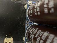
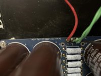
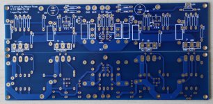
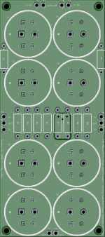
I want to install the ground break mentioned earlier but just noticed that my power supply board is different from the one in the build guide.
Is there a spot here where I could connect the thermistor ?
Also as a side note I lifted the ground with a cheater plug with no improvement so I'm thinking that the thermistor won't help anyway ?
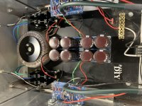
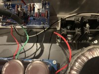
Looking at the pictures can you see any spots where I can make improvements that might eliminate the hum ?
I installed the 10R resistors on the input return lines with little improvement.
I want to install the ground break mentioned earlier but just noticed that my power supply board is different from the one in the build guide.
Is there a spot here where I could connect the thermistor ?
Also as a side note I lifted the ground with a cheater plug with no improvement so I'm thinking that the thermistor won't help anyway ?
Looking at the pictures can you see any spots where I can make improvements that might eliminate the hum ?
Attachments

@rtate
tight twisting of the wires helps a lot though in my case not enough.
I 've had the same problem with my F5 and ended up with a new toroid with four secondarys
quasi dual mono - that did it.
but some have solved the problem with good wiring - tightly twist your supply wires.
from what I have read here in the past years - especially the F5 is prone to cross chanel hum.
keep trying and good luck
A.
member bonsai's presentation is well worth a read
http://hifisonix.com/wordpress/wp-co...ound-Loops.pdf
http://hifisonix.com/wordpress/wp-co...ound-Loops.pdf
I had the same problem and tightly twisted wires and moving the input wiring further away helped, but the biggest change was when I started turning the toroidal transformer (with the amp off and unplugged!). I found a position where the hum is barely audible with my ear on the speakers (96dB).
My build is very close to the guide (including the thermistor between PSU ground and the case).
My build is very close to the guide (including the thermistor between PSU ground and the case).
Twist those wires. Pic of an example attached. Different boards for this F5, but shown for concept.
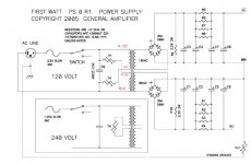
Is your PSU ground to Chassis ground sorted out? I'm not familiar with the PSU boards in the earlier pictures. They appear to be a dedicated CRC per channel. What I didn't see was a CL60 to chassis ground. I don't know if that board would have one CL60 per channel to chassis or the channel to channel ground tied together (star?) and one CL60 to chassis. Refer to the F5 PSU Schematic - TH1 CL60.
Once those are sorted out, play with moving the wires around while listening for hum. See the "headphone trick" in the link in the post #34.
Attachments
Ok , I have ordered a thermistor to use with the power supply.
I would like to try the Hum Breaking resistors seen on page 36 of bonsai's presentation but I don't know where to install them on the F5 circuit boards ?
Also will try to clean up the wiring and maybe rotate the transformer.
I would like to try the Hum Breaking resistors seen on page 36 of bonsai's presentation but I don't know where to install them on the F5 circuit boards ?
Also will try to clean up the wiring and maybe rotate the transformer.
You will probably need to break a track to install the resistors, can you post the schematic and board?
- Home
- Amplifiers
- Pass Labs
- F5 Ground Loop hum help please