was it?where you detail the power output of the F5?
Can you give me a date clue?
Is it main F5 Thread?
a Bell is the log of a ratio. After the telephone inventor.
A decibel is one tenth of a Bell. That explains the 10
The ratio of power (IV) is expressed in log of the power ratio and converted to decibels. This gives the standard formula power ratio = 10 log [P1/P2]
However when comparing voltage or comparing current we always maintain that same power ratio. That requires us to multiply the standard formula by 2, thus changing the 10 to 20.
Power ratios are 10log{p1/p2}
Voltage and current ratios are 20log{V1/V2} and 20log{I1/I2} as appropriate
thats funny zen mod.
Every math major knows that God was a mathematician before being a phycisist.
So the 20 comes from x*10 wher x = 1 for power ratios and x=2 for V and I ratios?
Every math major knows that God was a mathematician before being a phycisist.
So the 20 comes from x*10 wher x = 1 for power ratios and x=2 for V and I ratios?
just remembered a feature of using logs.
Adding is equivalent to multiplying.
log (20) = 1.3
So 20 *20 should be the same as 1.3+1.3
Let's check that
log (20*20) = log (400) = 2.6.
it checks out.
Now to look at the effect of that 2factor.
If adding two equal logs is equivalent to multiplying two equal numbers then multiplying a log by 2 must be equivalent to multiplying two equal numbers.
That is another way of saying squaring a number is equivalent to multiplying the log of that number by 2.
That 2 therefore is equivalent to squaring the voltages in that ratio. voltages squared is what appears in the power formula P= V^2 / Rload.
Napier was a clever (Scottish) lad.
I can add decibels together much easier than I can multiply voltages. division offers even more economy of thought.
My success..
Gents ,
I am just writing after experience of burning couple of fets and 47ohm resistor and .47ohms too.
Ok now I made 4 amplifiers all work great.
Follow this steps even I am not a Guru share what I learn.
Use 3.3K resistors instead 2.2K.
take two multimeter or 3. I am using 3 separate volt meters since I start making units for customers.
1 to check the voltage on speaker output. ( this is center 0 Voltmeter)
2 check the voltage across 2X .47ohms resistors.
Turn the Variable resistor voltage to 0.
be patient. turn the power on. Slowly start the VR1 and VR2 to rotate slowly by keep eye on all meters. ultimately u reach resistor voltage .6V and almost 0V on speakers.
Yes now you have done. 😎
A general question on bias
So I baised up my F5 to .4V over R11/R12 as an initial run to see how she goes. After cooking her for a while, playing a fairly random collection of tunes, bias had risen to ~.55V - still below the value of .6V that's the nominal target, but quite a rise nonetheless.
My question is -
Is the .6V drop over R11/R12 when the amp is idling or when it's pushing hard? And what sort of current draw should be expected when the amp has been pushing hard for a while?
Cheers for any responses.
aspringv,
from 0.4V to 0.55V is quite a jump.
Do you use 4k7 NTCs in the amp's circuit ?
If yes, how did you mount them?
A big clear picture would help...
from 0.4V to 0.55V is quite a jump.
Do you use 4k7 NTCs in the amp's circuit ?
If yes, how did you mount them?
A big clear picture would help...
In my shame...
Oh a picture, um, well...
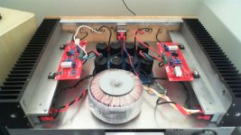
I bought the boards for this project quite some years ago, and well before I realized the full intellectual property ramifications of purchasing an F5 board from a chinese ebay dealer... <bows head in shame> and I was't overly keen on displaying my private diy faux-pas to the entirety of the internet. Pic's to follow shortly then.
Ahem.
Thermitors were originally thermal epoxied to the FET's , but after replacing them all recently after one FET went poof in a cloud of magic smoke, the thermistors are just kind of dangling nearish the FET's instead. I take it that the obvious first step would be to re attach the thermistors...
Oh a picture, um, well...
I bought the boards for this project quite some years ago, and well before I realized the full intellectual property ramifications of purchasing an F5 board from a chinese ebay dealer... <bows head in shame> and I was't overly keen on displaying my private diy faux-pas to the entirety of the internet. Pic's to follow shortly then.
Ahem.
Thermitors were originally thermal epoxied to the FET's , but after replacing them all recently after one FET went poof in a cloud of magic smoke, the thermistors are just kind of dangling nearish the FET's instead. I take it that the obvious first step would be to re attach the thermistors...
Don't judge me! <sigh>
Still deciding what sort of on off switch to utilise - I was going to put an illuminated toggle on the bottom panel to give a kind of subterranean glow and not mess up the front panel, but the legs are a bit short and I couldn't get fingers under... suggestions welcome!
Wiring is not final either... Heatsinks are conrad 300mm*75mm*45mm so she should be more than adequately heatsinked.
Attachments

Last edited:
those sinks looks a little smal. and combine with thermistors is not connected to the fets.
that might be the answer.
as there is no vents in the the chassis.
that might be the answer.
as there is no vents in the the chassis.
Last edited:
I tested heatsink temp at the time, and she was sitting in the low 50's, where ambient was probably 18C or so. Call it delta C of 35 or so. Temps certainly weren't into the 'don't put your hand there' levels.
sitting in the low 50's, where ambient was probably 18C or so.
Even a bit high for the 30-rib heatsink.
With decent high heels under the case, for plenty fresh airflow from the bottom of the heatsink, i'd think it should do better than 0.50C/W
Heatsink rating
Heatsink details below.
I like your call about elevating the chassis (high heels? now i'm thinking about lingerie for the chassis - I really don't want to try and explain -this- to the significant other!).
I guess whilst I tinker, a tweak to the chassis feet may be also in order.
Hmm, where to buy nice amp feet in silver/stainless/aluminium?
Attachments
Total size of the HS does look small.
That's +- 75mm height, if the transformer is 300VA?
Plus; the HS are of the deep "L" shape type so there will be a significant temp. difference between the "flat" where the FET is mounted and the ribs. You HAVE to provide good (inside of the) case ventilation there! The inner part of the "L" HS will emit tremendous amount of heat inside the case over a period of time, and there is nothing to vent the case as far as I can see?
Also, you don't want to over saturate those HS with bridge rectifiers mounted on them - they will work perfectly fine mounted on that thick Alu bottom plate.
I don't see a problem with bias control thermistors to be quite honest - maybe if you bend them over closer to one side of the FET and the HS underneath it? Touching the HS is fine, as long as it doesn't short the legs.
Edit: Just looked at the PDF - that's 0.6C/W for 80deg rise!!! You want no more than 30 deg rise. I'd guess a minimum of 150mm height for those same HS.
Last edited:
OK, next steps then
OK, I reckon I'll get some decent height feet for her (currently on 8mm or so rubber feet) and attach the thermistors back onto the fets with thermal epoxy and then I'll see where it's at and repost.
lazy search on easily available options for feet revealed Gold Speaker Stands - Pk.4 - Jaycar Electronics
and I'll take it from there (I need extra feet for the planned pre amp...)
thanks for the suggestions all!
Edit: Just looked at the PDF - that's 0.6C/W for 80deg rise.
Wrong number.
The 300 x 75mm reads 0.37 C/W at 80C above ambient.
Corrected for a delta C of 30 degrees, as per the Conrad derating graph, makes 0.49 C/W (aka : damn, i'm good)
Nothing wrong with an amp in drag (even the dictionary says so)
I used 400mm wide (40 ribs) x 55mm high heatsinks for Aleph J monaurals, 50W dissipation per heatsink, on 1.5'' high heels from ApexJr.
Last edited:
Now I see that tooWrong number.
The 300 x 75mm reads 0.37 C/W at 80C above ambient.
 Oops.
Oops.That I'm afraid I'll have to leave to the experienced 😉Nothing wrong with an amp in drag
- Status
- Not open for further replies.
- Home
- Amplifiers
- Pass Labs
- F5 Bias Problem