Well that all certainly took a tangent...
In point form -
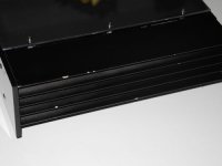
Feet - easily done, and it'll be a nice look anyway
Thermistors - thermal epoxy on order as we speak and I'll report back on how that works out for me
Amps in drag - er, no comment. 🙂
I'll get back to you all.
In point form -
Feet - easily done, and it'll be a nice look anyway
Thermistors - thermal epoxy on order as we speak and I'll report back on how that works out for me
Amps in drag - er, no comment. 🙂
I'll get back to you all.
Feet
eBay Australia: Buy new & used fashion, electronics & home d?r
should tarnish nicely to suit the 'rustic' look...
eBay Australia: Buy new & used fashion, electronics & home d?r
should tarnish nicely to suit the 'rustic' look...
Thermistors
Adhesive Heatsink Plaster for PC Hard Parts (5g) - Free Shipping - DealExtreme
for the epoxy; my last lot seems to have set in the tube...
Adhesive Heatsink Plaster for PC Hard Parts (5g) - Free Shipping - DealExtreme
for the epoxy; my last lot seems to have set in the tube...
Wrong number.
The 300 x 75mm reads 0.37 C/W at 80C above ambient.
Corrected for a delta C of 30 degrees, as per the Conrad derating graph, makes 0.49 C/W (aka : damn, i'm good)
Nothing wrong with an amp in drag (even the dictionary says so)
I used 400mm wide (40 ribs) x 55mm high heatsinks for Aleph J monaurals, 50W dissipation per heatsink, on 1.5'' high heels from ApexJr.
only 50W on alephJ?
anyway. its a BIG gap from 50 to 70W++
and 300-400mm depth.
1.3A bias with 24Vdc rails is not 70W++
Assuming the transformer is able to keep them at 24V.
Monaural amps usually have a heatsink on each side.
(i didn't mention how hot they run, 55mm heatsink height was the lowest i could go, height of the toroidal transformer is more than that)
Assuming the transformer is able to keep them at 24V.
Monaural amps usually have a heatsink on each side.
(i didn't mention how hot they run, 55mm heatsink height was the lowest i could go, height of the toroidal transformer is more than that)
Last edited:
and the difference from his 300mm to yours 400 mm is over 30%.
thats the same as your alephJ at around 80W inkl rectifier on the your sinks.
can they handle that?🙂
or the other way. his 70W+30% on your heatsinks=around 90W. doubt that will go very well🙂
thats the same as your alephJ at around 80W inkl rectifier on the your sinks.
can they handle that?🙂
or the other way. his 70W+30% on your heatsinks=around 90W. doubt that will go very well🙂
Last edited:
Your bridge rectifiers dissipate more than 7.5W at 1.3A bias ?
A GBPC25/35 at 40A still has less than 1Vf.
Which makes 1.3A average through two diodes less than 2.6W dissipation.
A GBPC25/35 at 40A still has less than 1Vf.
Which makes 1.3A average through two diodes less than 2.6W dissipation.
7.5Wx2=7.5+62=77. not very far from 70W.
or if you ment 3.75W pr brigde.
thats 69.5W
or if you ment 3.75W pr brigde.
thats 69.5W
Last edited:
if we take an imaginary heatsink of 300*55, then the heatsink I used is 36% bigger than that; Jacco's HS is 33% bigger. We can now start debating which has greater surface area, thicker base and the hypothetical efficiencies therein... There's even the degree of thermal coupling between the base and the HS to consider. And so on and so on...
Or I can just do it empirically, and whack some feet on her and stick down the thermistors (both of which would be best practice anyway) and see if I need to start drilling holes in my nicely finished enclosure!
I'll take option B and see how it works...
Or I can just do it empirically, and whack some feet on her and stick down the thermistors (both of which would be best practice anyway) and see if I need to start drilling holes in my nicely finished enclosure!
I'll take option B and see how it works...
We can model and simulate to our heart's content.
But ultimately, all modeling depends on on how well the model mimics actual operation.
What is the operating temperature of the devices? That's what matters.
But ultimately, all modeling depends on on how well the model mimics actual operation.
What is the operating temperature of the devices? That's what matters.
debating
It was just an example that low height heatsinks are a smart choice : wide & low is more efficient than narrow & tall.
(your Conrad heatsinks have more rib depth, btw)
I put distance rings between heatsinks and top/bottom panels, ensures decent airflow within the case, in particular near the heatsinks.
Skips the requirement for perforated panels, adding a vertical ridge at the case bottom further reduces dust issues.
(has the side-effect that a PS transformer can be taller than the heatsinks, and other trivia)
Single reason for my posting was merely to point at options to increase the efficiency of the heatsinks.
cursed text doesn't adequately convey meaning...🙂
I was attempting to use humor to pull the thread back to the topic - my apologies if that seemed like censure to anyone involved. I was trying to redirect us back form a random debate about appropriate heatsink size seeing as it seemed marginal at best in this case. Again, my apologies if my sense of humor did not come across clearly! :0
That's a nice idea; the spacing in the link between bottom panel and sides. I can easily pop some 3mm spacers i have handy between the bottom panel and the heatsink and not mar the aesthetics. Certainly a great idea to keep in mind for the next build. In this case, I'd be saddened to drill holes in the finished timber top, so thats a good alternative.
In short; thanks!
Dutch Diaspora
Where about's in Rotterdam are you? I have family over in the Netherlands, and have fond memories of visiting a number of times... It's been a while since I last visited though!
Where about's in Rotterdam are you? I have family over in the Netherlands, and have fond memories of visiting a number of times... It's been a while since I last visited though!
a nice idea
It's an old one.
An elegant vented panel implementation was in the Neumann A100.2 ,top panel flush with the heatsinks.
German serial manufacture from the mid '80s (MOSFET Class AB power amp).
The spacers also served to protect the chromed top panel from damaging.
I did get the humor part, hopefully Audiosan does too.
I live in Rockanje, five miles under the main harbour area, beach resort annex Rotterdam suburb. A bit similar to your place and Perth.
Attachments

As per I got directed, I guess this is now the correct thread rather than the one in which I posted my problem with the off-set running out of hands already with very low voltage (0.06V).
Yup, I guess I should read this thread thru before posting into it... 😱
Direct help to understand the problem would be nice anyway. Whichever thread. 😀
Yup, I guess I should read this thread thru before posting into it... 😱
Direct help to understand the problem would be nice anyway. Whichever thread. 😀
As per I got directed, I guess this is now the correct thread rather than the one in which I posted my problem with the off-set running out of hands already with very low voltage (0.06V).
Measured MOSFET resistances, in place on board, if it should matter:
G-D on both: 118
S-D on 240: 75
S-D on 9240: 69
G-S on both: 48
No power, no load.
Jusso, on the channel that is giving you problems, how much bias can you get with if you ignore the offset? (Do not attach a speaker when you do this!!)
.06 max bias with zero offset is quite odd. Check the value of the bias pots and bypass resistors.
Also, can you only get to .52v bias on the other channel? Can you get any more (with zero offset) ?
.06 max bias with zero offset is quite odd. Check the value of the bias pots and bypass resistors.
Also, can you only get to .52v bias on the other channel? Can you get any more (with zero offset) ?
I can get 0.6V or more if I ignore off-set on the bad channel.
I can get more than 0.52V on the good channel with zero off-set, but I just left it there to simmer.
Components are per schematics, from TechDiy, on Peter Daniels boards. Pots have at least same markings on them - I can re-measure them once again...
I can get more than 0.52V on the good channel with zero off-set, but I just left it there to simmer.
Components are per schematics, from TechDiy, on Peter Daniels boards. Pots have at least same markings on them - I can re-measure them once again...
- Status
- Not open for further replies.
- Home
- Amplifiers
- Pass Labs
- F5 Bias Problem