Hello every-one ! I had just purchased the F4 pcb's from our "DiyAudio-store" here. My question is this > how may I use the BrianGT style pcb's from chipamp.com, they were designed for a Aleph-30 or mini ? There set-up for pos + gnd + neg @ 6 x 22,000uf -CCRC per board. I would like to use 2 such boards for my F4 build with a 400Va 2 x 18 vac transformer which I allready have. Any help would be greatily appreciated Thank's 
Last edited:

Hello ZEN-MOD : My idea is to use 1 pcb per channel with a single transformer. I was thinking 6 x 10,000uf for each pcb, If you know the pcb's that I'm talking about, my question is what resistor values need to be used for CCRC to obtain the best performance for the F4 Psu ? Also is having 60,000uf per-channel enough or would more be better ? If so how much ? I have a very modest income and can't afford to experiment to much nor do I want to burn things up ect... Really just looking for some guide line to build my F4 the best way possible with the mix of boards I have. I have not ordered the Psu capacitors or resistors yet and can't afford to double order becuase I had made a mistake ect... They say measure twice cut once for best result. This is what I'm hopping to do with the help from other's who know alot more than I ! Any help would be help-full ! Again Thank-you .............😕
If you know the pcb's that I'm talking about, my question is what resistor values need to be used for CCRC to obtain the best performance for the F4 Psu ?
If you really want best performance, skip the resistor and install a 2mH aircore inductor.
Also is having 60,000uf per-channel enough or would more be better ?
plenty.
Again Thank-you .............😕
no worries. BUT, if you really want to learn, download PSUD II, input the parameters off of the component datasheets, and start simulating!
in case of using R there - use 0R1 - enough for decreasing ripple and not too much of increasing supply impedance
no worries. BUT, if you really want to learn, download PSUD II, input the parameters off of the component datasheets, and start simulating!
This needs to be in the forum sign-up document... 😉
'I understand that I need to download and learn to use PSUDII <tickbox>'
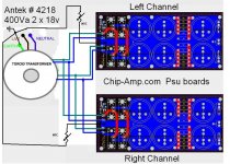
Zen Mod : Thank-you ! The board has a provision to parallel 5 - 3w resistors I'm gonna try 5 @ 0.47 ohm this should be close to 0R1. Also having not ordered the caps yet is 10000uf OK ? I can not down-load PSU designer II as I currently use a friends computer. Here is a picture of the board's I plan to use for a total of 120000uf @ 60000 per channel please advise if this is OK >
An externally hosted image should be here but it was not working when we last tested it.
Last edited:
Not trying to get off topic but I had found this soft start and wondered what everyone thinks either good or bad for the F4 > soft start electronics for audiophile hifi audio amplifiers : avondale audio
I use a single CL60 in series with the primary winding - works like a charm. Didn't know Nelson uses two.
Hannes
Hannes

Bump !
If the above layout will work, what would be the best way to install ground's ect... Also should the transformer secondaries be grounded ?😕
If the above layout will work, what would be the best way to install ground's ect... Also should the transformer secondaries be grounded ?😕
Last edited:
Zen Mod, Here is the link for data sheet ! http://www.antekinc.com/pdf/AN-4218.pdf Its actually the AS-4218 which is the shielded version but same spec's.
Last edited:
Zen Mod Thank-you ! This makes me really happy, With the pcb layout there are holes or pads at the other end for ground can I use them w/o any problem ? Also what about hum or noise will I be OK ?
you're really squeezing da lemon ..... 
other end ......... use for wires going to amp pcbs and output ( speaker gnd)
say that - at other end of pcb is your central gnd point
I have simple idea - go to 6moon or anywhere else - look for origigi F4 highres pics and study - how Master itself ( known in certain circles as Papa ) does that ...... elegantly and without making it complicated
again ...... wire xformer wires exactly as on that little sketch ;
use already famous bulb thingie in series with mains , while testing it for first time .
if that isn't familiar to you - just search for "bulb tester" here at diya
also - you can search for "Papa's Koan" for some other pictures of F4
Last edited:
- Status
- Not open for further replies.
- Home
- Amplifiers
- Pass Labs
- F4 Psu help needed please !