Decided to replace one of the faulty board with another board.
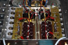
Was finally able to fire up the F4 and set up the bias - approx 200mv resulting in the heat sink temperature of 59deg C.
Even my wife commented that the F4 sounds superb. However approx 2hours into using the F4, the fuse blew.
Checking the boards - I found 1 of the 3W resistor burnt / probably resulting from the fact the corresponding mosfet was not properly attached to the heat-sink
Other than the 3W fuse, is that corresponding mosfet also dead? (looks kinda brown around the edges) Any other components that will need to be replaced?
thanks
her shann
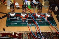
My F4 and Aikido prosject
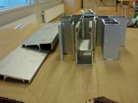
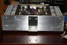
This is my F4 amplifier project. Later on Aikido will be added into the same chassis.
Heatsinks to a class A amplifier cost a lot of money, so I went to a junk merchant in the nearest town. Here I paid a reasonable price per kilo aluminium and for the cutting.
(I was to late to participate in the group-buy on DiyAudio)
Attachments

My F4 and Aikido project
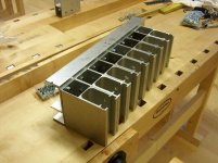
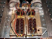
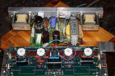
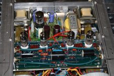
The PCB is from “cviller from Denmark”. I found his solution to be the best on my DIY heatsink with regard to a balanced spread of heat.
No problems either with DC or bias.
The most “thrilling”: How would my selfmade heatsink behave??
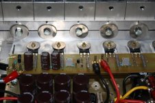
Suprisingly well. After one hour I could easily keep my finger on it without any unpleasantly. The first minutes hottest where the FETs
are mounted, but after one hour very well spread over the hole heatsink.
I think I could easily increase bias setting from 250 mA to 300 mA
without problems. But I am not sure I have any benefits of doing that, or what will you experts out there says??
The PCB is from “cviller from Denmark”. I found his solution to be the best on my DIY heatsink with regard to a balanced spread of heat.
No problems either with DC or bias.
The most “thrilling”: How would my selfmade heatsink behave??
Suprisingly well. After one hour I could easily keep my finger on it without any unpleasantly. The first minutes hottest where the FETs
are mounted, but after one hour very well spread over the hole heatsink.
I think I could easily increase bias setting from 250 mA to 300 mA
without problems. But I am not sure I have any benefits of doing that, or what will you experts out there says??
Attachments


My F4 and Aikido project
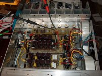
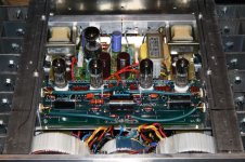
This is a very fine amplifier with at very big soundstage. The unit is ment to be take care of the 60- 600 Hz range on my
Magnepan 1.6 loudspeaker. The crossover is a DCX 2496(modded)
But I have a ripple problem in one channel.
I have started a new thread on this forum (Tubes): "Grounding Aikido and F4" where I try to describe this problem.
May be it would have been a better idea to ask other members
for help in this thread??
I do hope for some good adwises before my hair turn grey.
Attachments
spencer said:I have reduce the source resistor to 0.245 ohm (0.51//0.47) due to good match of the mosfets.
Did you just reduce the value of the source resistor until the voltage was a certain percentage different on all the MOSFETs? What's a good guideline on how different the voltage drop across resistors can be and still have good performance?
- Home
- Amplifiers
- Pass Labs
- F4 power amplifier