The most interesting discussion about a preamp for the F4 can be found here:
http://www.diyaudio.com/forums/showthread.php?s=&threadid=101152&perpage=10&pagenumber=1
Hugo
http://www.diyaudio.com/forums/showthread.php?s=&threadid=101152&perpage=10&pagenumber=1
Hugo
Netlist said:The most interesting discussion about a preamp for the F4 can be found here:
http://www.diyaudio.com/forums/showthread.php?s=&threadid=101152&perpage=10&pagenumber=1
Hugo
Thank u for that !!! the speed of this thread was almost quicker then the speed of light !
Anyone have an update about his F4 ? no ok I'll give it a try
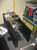
Today i received my secondhand heatsinks, the sk56 from fischer at about 200mm height they will do 0,3 C/W. I also using these on my aleph 5's. I planning to build first one stereo F4 and later on i will build an other one so I can use them balanced.
I'm currently searching for a nice toroid 300VA or something like that.
Attachments
analogair said:.....................
I know they should be rated as having a sencitivity at 96dB/1m/ 8w
................
93db/1m/4W
90db/1m/2W
87db/1m/1W
Jaac TheMaster said:the speed of this thread was almost quicker then the speed of light !
Blame Zen Mod.

I have split everything past post #530. Credit for spotting goes to cviller. If anything needs to be put back into this thread, just mail me the post numbers and I'll comply.
/Hugo
BrianDonegan said:Jaac TheMaster-
Nice bookends!
thanks !! A welder, some iron é voila
analogair said:.... a pair of B&W Matrix 801 Series 2
I know they should be rated as having a sencitivity at 96dB/1m/ 8w
I somehow am pretty sure that the are harder to drive than that, so if someone have some real life specs...
I have been reading a lot of articles about my speakers, and some writes about them having lower sencitivity than the mentioned 96dB/1m/8w.....Anybody ?
Zen Mod said:
93db/1m/4W
90db/1m/2W
87db/1m/1W
84db/1m/ .50W
81db/1m/ .25W
78db/1m/ .125W
.
.
.
I know the math, but thanks anyway Zen Mod
Sorry for the off topic guy's

Thanks to Peter Daniel I corrected one mistake on my PCB for this amplifier - Q2 was inverted. Now everything is OK. For those who made this PCB in previous version - all you need to do is invert this transistor.
http://www.unisonus.com/pdf/f4_r0_pcb.pdf
http://www.unisonus.com/pdf/f4_r0_top_mirror.pdf
http://www.unisonus.com/pdf/f4_r0_sch.pdf
http://www.unisonus.com/pdf/f4_r0_pcb.pdf
http://www.unisonus.com/pdf/f4_r0_top_mirror.pdf
http://www.unisonus.com/pdf/f4_r0_sch.pdf
What effect would having Q2 inverted have on the amp? Would that mean it was not working as a push-pull amp and (if I understand correctly).
Would there be any damaged components I should check for (aside from Q2).
I have built Veteran's layout, but since my speakers are all very inefficient, I haven't put many hours into running it so far
Thanks,
Stephen
Would there be any damaged components I should check for (aside from Q2).
I have built Veteran's layout, but since my speakers are all very inefficient, I haven't put many hours into running it so far
Thanks,
Stephen
Darry said:Veteran,
Why do you connect the diode D3 to +23V and D4 to -23V ?
In the schematic of the version R0 of M. Nelson Pass, D3 is connected to the drain of Q1, to R6 and P2. D4 is connected to the drain of Q2, to R7 and R5.
Darry
I'm basing on R0 schematic from 4/17/2007. Those diodes are directly connected to (-) and (+) rails.
Additional resistors if you want to have some small separation from output stage
. Take a look at my schematic and if you don't want to use them - place jumpers.A correction to initial schematic has been done here: http://www.diyaudio.com/forums/showthread.php?postid=1185900#post1185900
Sorry Veteran, you have also reason.
I had the enclosed schematic R0, also from 4/17/2007 with different connection for D3 and D4 diodes.
Maybe that Nelson will say us what is the good schematic !!!
There is also a little difference between the schematic of the service manual and the R0 version.
On the service manual, the input is on R1 and for the R0 version, the input is between R1 and R2.
How to connect input ?
Attachments
While both these schematics work fine, neither is the correct
version.
Peter is correct:
navigate to www.passlabs.com/np and download the f4r0 pdf.
You will note that D3 and 4 are connected slightly differently.
version.
Peter is correct:
navigate to www.passlabs.com/np and download the f4r0 pdf.
You will note that D3 and 4 are connected slightly differently.
Perhaps this is too off the subject, but...
Since the biggest hassle is the enclosure,
and the biggest expense is the PS,
and since the F4 is an odd duck (a really great odd duck),
I'm thinking of building in another two channels (of a more conventional)
amplifier, utilizing the same case and power supply.
What, in your opinions, should that other amp be?
I'm leaning towards a Peter Daniel Chip amp.
Any ideas...
They wouldn't necessarily be used together, but perhaps the F4 as full range and other driving supertweeter or sub.
-Thanks - Marsupialx
- Home
- Amplifiers
- Pass Labs
- F4 power amplifier