F5 will do
you'll probably don't even need doubled outputs
But where will all the current come from, Mr. ZM?! Can we get an improved Ohm's Law instead?
Wrote with Rob, the manufacturer in Australia, and he agrees it will be "a trial and error exercise" about Firstwatt amps. The electrostatic drivers are leaving Italy tomorrow! Exciting stuff! Considering that they won't play more than 250-15 000Hz, maybe they won't need monster levels of current. 🙂
If the standard F5 can drive them, I can be pretty sure that the standard F4 will work.
If the standard F5 can drive them, I can be pretty sure that the standard F4 will work.
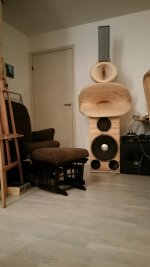
The 25W Firstwatt F5 clone did do very well with the panels. I need like 25% volume instead of the 15% for the horns. 🙂 Now I have to decide on another F5 or F4. Gotta love a 7 ft speaker.
Attachments
Last edited:
F4 has significantly more current capability than the F5. I suspect it will work MUCH better then the F5.
Thanks, I noticed an improvement with the electrostatic panels when going from a 2A3/6SN7 tube amp to an F5, and I suspect it has to do with current capacity. I will go for the F4 if it has even more. The F7 will be interesting to hear also, whenever that is released.
Last edited:
F4 as current booster
In the manual NP talks about the possibility of using the F4 as current booster for a low powered amp. I've been lucky enough to reserve the VFET kits. Ideally I'd like to use the VFET amp to drive the compression drivers of my JBL M2s. However I don't think the VFET amp will have enough power. I already own an F4 ( well 2 actually, but for space reasons I only want to use one) and so I'm thinking about the possibility of using it as a "follower" to the VFET.
I'm wondering how much this might detract from the (reported) superiority of the VFET amp. Anybody have experience of using an F4 in this mode of operation?
If you look at your manual you see the impedience of your M2 high frequency driver is a nominal 20 ohms. In your case trying to get more power from that Vfet amp runing it into the F4 won't work out as you hope instead you will end up losing .3db !
If you look at your manual you see the impedience of your M2 high frequency driver is a nominal 20 ohms. In your case trying to get more power from that Vfet amp runing it into the F4 won't work out as you hope instead you will end up losing .3db !
OK, I need to do some reading so I can understand that! Also, Although this is a pseudo active speaker (amplification is not inside the cabinets) there is a pad before the CD that apparently eats 9db.
The preamp I'm building for my F4 has some optional output capacitors for selecting tone or whatever. I'm planning on experimenting with running both line outputs simultaneously, connecting to each side of the F4. Each side would be fed the output from one capacitor or the other. So they're getting similar but not identical signal. (I suppose this could be modeled as a really crappy jumper.)
And then tying the speaker outputs together, as when running paralleled. Mostly because I'm curious what will happen, not because I think it'll make some improvement in the sound. Unless of course the answer is "if you can cut the power fast enough, you may be able to keep your new amp from catching fire." Then I probably won't try the experiment.
And then tying the speaker outputs together, as when running paralleled. Mostly because I'm curious what will happen, not because I think it'll make some improvement in the sound. Unless of course the answer is "if you can cut the power fast enough, you may be able to keep your new amp from catching fire." Then I probably won't try the experiment.
Since watching Papa's BAF 2016 speech I have decide to add this amp to my collection. I have an Antek 20V transformer already so I am planning on using it. Does anybody know any changes that need to be made with the slightly higher voltage. I have used a 20V on other builds without any issues. I have not read the entire thread but from skipping around I have found that one should use the original NP schematic for part selections with the R8 value of 27K vs the store BOM of 22.1k the one most scrutinized. Opinions?
I think there is nothing to change.
I'm using a same toroid (4x25VAC/1000VA) as on the picture at top right without any issues for years to drive four F4. These are stock F4s on Veteran's boards. I have about +-32-33VDC rails, with something about 1A/FET. So the whole thing consumes more than 650W.
In fact, there was a failure, with some smoke. It turned out, it was one of the eight 50A bridge rectifiers, one of the diodes went short circuit.
There was no failures with JFETs and FETs.
Quite a beast, heating well.
https://onedrive.live.com/?cid=E894CB7D50B65FBF&id=E894CB7D50B65FBF%211692&parId=E894CB7D50B65FBF%211672&o=OneUp
few volts (rails) up or down - nothing needs to be changed
regarding R8 , as always - I'm too lazy to search for ref. schm.
however , I can't remember that I made any change in Papa's Koan , ref. to F4 rev.0 6/4/07
leave R8 at 27K , if you can't bias enough , decrease R9 (10K) to first lower value
regarding R8 , as always - I'm too lazy to search for ref. schm.
however , I can't remember that I made any change in Papa's Koan , ref. to F4 rev.0 6/4/07
leave R8 at 27K , if you can't bias enough , decrease R9 (10K) to first lower value
When first powered up, I have some issues, because with stock resistor values, It can't be set quiescent current. Ie, FETs can't turned on. I have changed some resistors around TL431 I can't remember which ones, it was several years ago, and I have some dementia. Probably R8-R9 as ZEN mentioned it..
Thanks guys. I pretty much knew the answers but it is alway reassuring for someone else to agree. Nelson has stated many times the reason he chooses 18V toroids is because he bought 2000 of them years ago. I will maybe need to adjust bias somewhat lower depending on heatsink temps is the way I saw it.
I fired up my F4 yesterday without any problems. I used lsj74's along with 2SK170's without a problem. I bought 8 of the lsj74's and matched them to the 20 or 30 2sk170's I have been hoarding. There was no problem biasing it up using a 27K ohm R8 and 10K R9 per NP schematic. I took a lot more time matching the mosfets with this build. I bought 15 of the IRFP9240 and all of them were closely matched and could actually be used without matching. The IRFP240's were not so close but out of 15 it was easy to get 2 sets of 3 that matched. I have a number of pres to try and so far all three that I have tried sound very good. Very nice addition to my other 5 FW clones.
F4's PSRR and EMI sensitivity?
When I was a boy at my father's knee, he taught me that feedback reduces noise and distortion and, by inference, reduces the circuit's sensitivity to noise.
Now, I am building an F4 (single ended and no feedback) with an Impasse front end in the same box. Of course, that means that I will have 650 VCT trafo and psu with all the EMI potential issues in that same box. The Impasse has pretty good PSRR and CMRR. I just don't know what to expect with the F4.
Does anyone know how sensitive the F4 is to EMI and how good is the PSRR? In other words, am I nuts to be putting these in the same box? Would it be OK with some EMI containment? Or should I look to putting the Impasse psu in another box?
I am no expert in these areas, so if you are, please reply in small words suitable for a beginner EMI student.
Jac
F4 is a nice, flexible and multi purpose power buffer amp.
You can play with any front end and voltage amp that you can think of.
You can play with any front end and voltage amp that you can think of.
I had build another pair of F4 hope to make F4X but had issue with one channel.
First channel worked perfect but I'm getting 18Vdc output offset from the other channel.
The Vds reading on the NPN output mosfet measures 4.3Vdc while on PNP measures 43Vdc.
What could possibly cause this imbalance?
Thanks in advance!
First channel worked perfect but I'm getting 18Vdc output offset from the other channel.
The Vds reading on the NPN output mosfet measures 4.3Vdc while on PNP measures 43Vdc.
What could possibly cause this imbalance?
Thanks in advance!
Last edited:
- Home
- Amplifiers
- Pass Labs
- F4 power amplifier