Hi All,
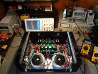
Getting close to finishing my dual mono F4 clone. It's only been powered up for about an hour and I was listening to it for 15 min or so. Sounds great with the tube pre-amp that is also mostly done. I'm going to let the F4 run a few hours on the bench and re-adjust the bias and offset in preparation for a full listening session tonight. HP339 is saying THD: ~0.0078% at 1 watt into 8 ohm. Real number is likely lower than that as I think the notch filter on the HP needs some work.
The case is the diyaudio deluxe 4u.
Anyway, thanks to Papa and everyone else for all the info you've posted to this site. Without it I'd still be listening to store bought stuff.
Attachments
Last edited:
every stereo F4 deserves proper XLR on back plate

Don't worry. 30 minutes with a saw and I can switch the RCA to XLR if/when I need to.
Here's a question for ya
Look at the second waveform in my picture, 1st post (1st waveform is 1khz input). This is the HP distortion monitor output. This the signal sent to the meter after the notch filter. See how much fundamental frequency is in the signal? Shouldn't that have been removed? and isn't it throwing my measurements off?
thx
well - you must explain your measurement method , so we can decide what's lousy - your building , or measurement skills

Well, lets disregard my analyzer question, probably not the right forum for that.
As for the F4: first listening session last night was most enjoyable. It sounds great in my system. Just what I was looking for.
As for the F4: first listening session last night was most enjoyable. It sounds great in my system. Just what I was looking for.
Quick one: are two 2*26v 120va transformers good to power the f4?
I still have them lying around but am not sure regarding too high voltage and too low power...
I still have them lying around but am not sure regarding too high voltage and too low power...
120VA is limiting factor - you'll need to decrease bias
also - Jfet's are approaching tricky voltages - you'll need to take care of their Idss .....
so - either degeneration or cascooding
also - Jfet's are approaching tricky voltages - you'll need to take care of their Idss .....
so - either degeneration or cascooding
so - either degeneration or cascooding
Has anyone ever posted an F4 schematic with cascoded JFETs? This could be interesting to see alongside the recent F5 Turbo excitement. F4 Turbo V1?
This would be another way to raise the voltage, at least to the max voltage of the BA-3 front end, whether running balanced or SE.lacking B3 , best thing for now is combining BA3 Balanced front end with input buffer-less balanced F4 .........
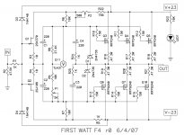
Out of curiosity, would this be achieved by omitting R1-4, Q1-2, D3-4? What about C1-2, still needed?
Last edited:
Has anyone ever posted an F4 schematic with cascoded JFETs? This could be interesting to see alongside the recent F5 Turbo excitement. F4 Turbo V1?
probably yes ; pretty trivial ( read - cut'n'paste jobie)
...... R1-4, Q1-2, D3-4? What about C1-2,.......
speaking of which schematic , exactly ?
speaking of which schematic , exactly ?
The F4
Attachments
I built my headphone amp using attached schematic - also added Jensen JT-123-ALCF as Nelson recommended as interstage transformer (posts 3397 -3400.)
I was just kindly gifted some 2Sk2013s and 2Sj313s. Can they replace the IRF510s and IRF 9510s? I have these currently biased at 350mA
As always thanks.
Bob
I was just kindly gifted some 2Sk2013s and 2Sj313s. Can they replace the IRF510s and IRF 9510s? I have these currently biased at 350mA
As always thanks.
Bob
Attachments
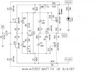
YEs, although not optimal. tHey should perform better than IRF. THe F5 juma built with them had bias at about 500mA. Big thing is, you cant push them hard, as I believe they are only rated for 1A, so dont really want them going AB.
As I remember 🙂 I may have to adjust R8 or R9 for biasing and R6 or R7 for offset. I ended up with R9 at 5k and R6 at 8k
Best
Best
- Home
- Amplifiers
- Pass Labs
- F4 power amplifier