It will be interesting to see will you'll get better gm symmetry with those smaller latfets, btw they have 20 times less gm than 1058/62.
Its a good question.
I have been exercising my test equipment to try to answer the question about gain symmetry.
Preliminary results tell me that the gain symmetry of the LATFETs in my hand is within a few percent of each other.
So, after some head scratching, I have arrived at the conclusion that your post in #50 of this thread is the solution. I will use a cap to bypass some of the resistance biasing the larger Vgs LATFET.
So, this will violate the no-capacitor goal, but if that makes the open loop gain more symmetric, I think that is a good trade.
I will lash that up and see how it measures.
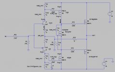
In the most recent schematic, R17 will become a 100 ohm pot bypassed by a capacitor. This pot will be called the symmetry pot. R6+R7 will remain as the bias pot that will match the resistance needed to bias the other LATFET. M2 will formally be called the bias voltage hog.
This is the reason you want FETs matched for Vgs and gm. If you have matched FETs, you can make simple complementary amplifiers that have good open loop symmetry.
This is the reason you want FETs matched for Vgs and gm. If you have matched FETs, you can make simple complementary amplifiers that have good open loop symmetry.
After some more thinking, I have added another pot. All of these are now 100 ohm pots: R5, R18, R6, R17.
R17 is the new symmetry pot that is bypassed with a cap.
R6 is a pot that should be set identical to R5.
R18 is a pot to match the Ids of the JFETs.
There will be 1 ohm current measurement resistors for each JFET and for one of the LATFETs.
The pot settings will be dependent on each other, and most likely a pain, but this is DIY. Viva la pot.
I will start with a new and larger board.
Attachments
I found the asymmetry problem. I discovered this while building a BA3 preamp for a friend. My signal generator has enough of a DC offset to throw the bias voltage of each output transistor off by 20mV. I measured this with a DMM on each output transistor gate.
It took quite a bit of head scratching and troubleshooting to convince myself to investigate the output bias at rest vs bias with a signal applied.
Once I get my friend's BA3 preamp finished, I will go back to the F4 beast using a cap in series with my sig gen.
It took quite a bit of head scratching and troubleshooting to convince myself to investigate the output bias at rest vs bias with a signal applied.
Once I get my friend's BA3 preamp finished, I will go back to the F4 beast using a cap in series with my sig gen.
Yes, the input offset could be the problem, but I don't think it has much effect on uneven halfwave amplitudes...
Yes, the input offset could be the problem, but I don't think it has much effect on uneven halfwave amplitudes...
au contraire, I witnessed it.
I connected two DMMs measuring DC volts. Each from a rail to the gate of the nearby OPS device gate.
Take a reading with OPS idling and DC offset at minimum.
Turn on the sig gen. Each gate moves 20mV. One gate increases 20mV and the other decreases 20mV. Multiply that 20mV by the gain of each transistor.
For the BA3 that I am building, with the bias at 45mA, that 20+20=40mV imbalance at the gates is why the output is asymmetric.
You`re right, if you are balancing the circuit with trimmers in open loop, while there is a input dc offset, than the circuit won`t be balanced for AC.
- Status
- Not open for further replies.
- Home
- Amplifiers
- Pass Labs
- F4 Beast with hundreds of amperes