Here is the next thing to solve. The negative half of the amp has more gain than the positive half. I believe the problem is the P-channel puck's gain is much higher than the N-channel puck. The logical solution would be to degenerate the P-puck. I do not want to do that since I want unlimited current in both halves of the OPS.
I am going to try to degenerate the 2SK1058 that is driving the P-channel puck to see if I can make the open loop behavior of the amp symmetric before applying negative feedback.
I am going to try to degenerate the 2SK1058 that is driving the P-channel puck to see if I can make the open loop behavior of the amp symmetric before applying negative feedback.
Attachments
Maybe it's not up to pucks, have you tested the gain stage alone, in like BA3 configuration, to see is clipping simetrical, what is a shape of sine etc.?
Last edited:
Maybe it's not up to pucks, have you tested the gain stage alone, in like BA3 configuration, to see is clipping simetrical, what is a shape of sine etc.?
Good idea. I will have to short the bias spreader to check the gain stage. In the meantime, I may have smoked a transistor or a pot/resistor.
Here is the next thing to solve. The negative half of the amp has more gain than the positive half. I believe the problem is the P-channel puck's gain is much higher than the N-channel puck. The logical solution would be to degenerate the P-puck. I do not want to do that since I want unlimited current in both halves of the OPS.
I am going to try to degenerate the 2SK1058 that is driving the P-channel puck to see if I can make the open loop behavior of the amp symmetric before applying negative feedback.
1. Disconnected the OPS
2. Shorted the bias spreader
3. Scope shot looks just like the above scope shot
How to reduce the gain of the negative rail connected LATFET?
When you shorted the the bias spreader, have you conected a load resistor from that output point to ground and what value? It is lot easier when you post the schematic, of what you have tried..
It is this with:
Bias spreader shorted
OPS disconnected
No load
The scope picture with all of the above is just about exactly what it is with the bias spreader and OPS connected.
I am considering changing the 20R pot connected to the sources of K170/J74 to a 200R pot.
Bias spreader shorted
OPS disconnected
No load
The scope picture with all of the above is just about exactly what it is with the bias spreader and OPS connected.
I am considering changing the 20R pot connected to the sources of K170/J74 to a 200R pot.
Attachments
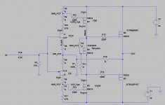
Dont change that pot, it should be 20R. What are R18 and R17 for? Btw if you want them, they should be in the same place at both sides, right after jfets drains, wich is not the case for lower jfet, look at that schematic little better. Anyway, when you short the bias spreader, connect for example about 10k from the output node to ground and then measure. Before that check the bias and offset...
The larger resistor value you connect on the output node (in this case drains of latfets), more open loop gain you get, and more nonlinearity you see, the circuit is far more sensitive to all kinds of things..
In the proto version, it could be usefull to connect 1 ohm resistors in series of latfet drains to measure the current easy way.
Last edited:
Dont change that pot, it should be 20R. What are R18 and R17 for? Btw if you want them, they should be in the same place at both sides, right after jfets drains, wich is not the case for lower jfet, look at that schematic little better. Anyway, when you short the bias spreader, connect for example about 10k from the output node to ground and then measure. Before that check the bias and offset...
The larger resistor value you connect on the output node (in this case drains of latfets), more open loop gain you get, and more nonlinearity you see, the circuit is far more sensitive to all kinds of things..
In the proto version, it could be usefull to connect 1 ohm resistors in series of latfet drains to measure the current easy way.
R17 and R18 are 47 ohms as per the schematic. R18 is not needed. R17 allows the pot to be centered.
I could use 200 ohm pots, but I believe that the result would be as it is now.
I will load the LATFETs' outputs to see if that makes a difference. The fact that the complete amplifier open loop behavior is identical to the first two stages leads me to believe that making the unloaded first two stages as symmetric as possible is a good thing.
Jfets and also latfets are not true complements, plus, you have pots at jfet drains that are not in the same position that all affects open loop linearity. On some schematics of F5 variant and incarnations you have caps to bypass one half of resistance of jfet drain pots, maybe it could help..
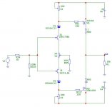
What about this solution for lowering VDS? I`m using zener over jfet in my amp (similar but not complementary) and have no noise issues.
It may be good to bias the latfets at about 100mA for best tempco. R80 and R95 are just for easy bias measuring.
I am open to any and all suggestions. I did add a 1 ohm resistor in the source of the 2SK1058 and I measure current there.
Can yo tell me the reason for the zeners in series with the K170/J74 JFETs? Is this sort of a shortcut to drop some voltage without resorting to cascode BJTs?
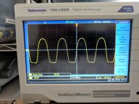
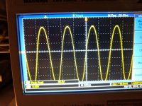
I ran the LATFETs bias slowly up to 100mA with less than 30mV offset. Attached is the scope shot of the output at the LATFET drains. 36V p-p. More than 4 divisions on the negative swing and 3 divisions on the positive swing. So, I need to burn some gain on the negative swing.
I am going to go though my stash of LATFETs and look at gm at 50mA and at 100 mA for all of the P and N LATFETs and see if can find any close matches for gm for any P-N pairs.
Ok,looks good. Zeners are just an idea for lowering Vds if you use higher rails.
Actually, it does not look good. The gain on the negative half cycle is more than the positive half cycle causing asymmetric clipping. I am looking for a way to correct that without having to use matched LATFETs.
I meant looks good for now ☺ it's open loop after all and almost only large 2nd harmonic. You could degenerate one latfet to equalise half cycles or experiment with different idle current of latfets, I don't have other ideas right now..
Zen what is CC, constant current? In this case, zener is opereting at about 6mA at idle +/- few mA max durig the peak to peak swing, I don't think it's deviating the transfer function of jfet, at least not in simulation, I can't hear the difference, that is for shure ☺ Yes you could bypass the zeners but only with rails 24V or less,because of 2SJ74...
I'm just giving the ideas, I've allready tried in similar toplogy amp, in real life.
2prs of K213/J76s are on the way to you. The pair should work nicely at 50mA bias range.
Thank you !!!
It will be interesting to see will you'll get better gm symmetry with those smaller latfets, btw they have 20 times less gm than 1058/62.
- Status
- Not open for further replies.
- Home
- Amplifiers
- Pass Labs
- F4 Beast with hundreds of amperes