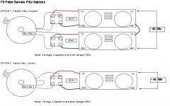
I think both are ok, but the major advantage of option 1 is that you can use 35V rated caps - in 15000uF or greater these are pretty widely available..... but to use option 2 you would need caps rated at probably 63V and these are much dearer.
someone else check this though.....
Fran
someone else check this though.....
Fran
The pic is correct 😉
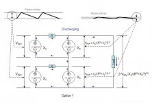
The advantage...you see twice the parts in option1, you get twice the magic. Twice capacitance gives half output ripple. Of course it's also correct that you can use 30V caps in option one (as every cap sees only half the voltage compared to option2 where you need about 60V caps) which allows you to use even larger caps (for a given diameter).
Wether you need that is entirely up to you.
Have fun, Hannes
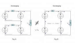
Looks like the caps in option 1 are in series, electrically. If the caps are 15.000uF and connected in series, then:
C equiv= 15.000:2= 7500uF. Looks like pretty wastefull to me.
Option 2 looks mucho better.
🙂
C equiv= 15.000:2= 7500uF. Looks like pretty wastefull to me.
Option 2 looks mucho better.
🙂
thanks for replies, i realize the question may be trivial but a little support is always appreciated.
I believe setup is CRC and therefore capacitors are not series. thanks again.
pathmark
I believe setup is CRC and therefore capacitors are not series. thanks again.
pathmark
Shame on me, I completely missed that option1 is not intended as split-power supply 
If somebody wants to use that (opt2) for a single rail and ground, steenoe is of course correct. Capacitance is halfed, not very funny.
Have fun, Hannes
If somebody wants to use that (opt2) for a single rail and ground, steenoe is of course correct. Capacitance is halfed, not very funny.
Have fun, Hannes
oops...i just got it! As wired in option 1 the capacitors from the two boards are in series, even though each board individually is not.
Ok looks like option 2 with higher value caps!
pathmark
Ok looks like option 2 with higher value caps!
pathmark
 . . . ???
No, never.
Kindly understand that my writing is not to do back-firing anyone 🙂
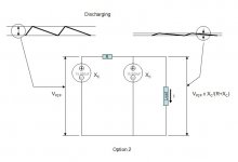
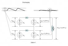
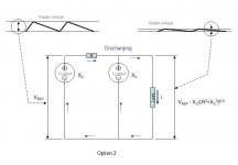
I have also interested in the different effect between Option 1 and Option 2. I have focused my bloodshot eyes to the drawing long time till I have finally made a burnt hole on the drawing. The main purpose of the CRC filters is to make the ripple voltage as flat as possible. If I see the two options on the same boundary condition, I see the same ripple reduction effect between the two options. I conclude that any option is equally okay with respect to the ripple voltage reduction effect. The difference might be in the building cost tho . . .
Cheers,
>>🙂<<
babo...
if i understand steenoe post, option 1 causes capacitors to be series, reducing the total effective capcitance.
In option 1, using 15000uf would yield 7500uf-R-7500uf.
While in option 2, the result would be 15000uf-R-15000uf.
Is this correct? If yes, then ripple would be less in option 2.
pathmark
if i understand steenoe post, option 1 causes capacitors to be series, reducing the total effective capcitance.
In option 1, using 15000uf would yield 7500uf-R-7500uf.
While in option 2, the result would be 15000uf-R-15000uf.
Is this correct? If yes, then ripple would be less in option 2.
pathmark
Pathmark said:
In option 1, using 15000uf would yield 7500uf-R-7500uf.
Steen's comment on the capacitance is right.
And, I inperprete Option 1 as 7500uF-(R+R)-7500uF.
Cheers,
🙂
Please ignore post#10.
It's too late local time.
I need to go to bed.
I will try to re-write it tomorrow. Thanks . . .
It's too late local time.
I need to go to bed.
I will try to re-write it tomorrow. Thanks . . .
Pathmark said:babo...
if i understand steenoe post, option 1 causes capacitors to be series, reducing the total effective capcitance.
In option 1, using 15000uf would yield 7500uf-R-7500uf.
While in option 2, the result would be 15000uf-R-15000uf.
Is this correct? If yes, then ripple would be less in option 2.
pathmark
That is spot on😉
🙂


Hi Babo. Nice graphs that illustrate the issue very well.
Just think about it, Papa uses option 1 in some of the F-amps, as far as i recall😉 ( those with singlerail supply)
🙂
Just think about it, Papa uses option 1 in some of the F-amps, as far as i recall😉 ( those with singlerail supply)
🙂


One reason I'll bet Papa uses the approach he does (option 1) is that he can use the same power supply as he uses on the other F's. with a slight mod.
So is the final word that it is indeed better to use option one?
I'll let you think about it another night Babo 😉
IF you doubled the size of the caps in option 2 would it be as good as option 1 . How about resistor values? Double them?
Option 2 uses only one bridge and I use IXIS which are pricey..
Mark
- Status
- Not open for further replies.
- Home
- Amplifiers
- Pass Labs
- F3 PS Options using PD boards