7-21-21 Update
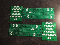
The test boards arrived last Friday and they look good. The test boards do not have ENIG finish to keep costs low, but the final boards will have the ENIG (gold) finish on all the solder pads. I will be somewhat delayed in building the boards while I deal with some major internal engine problems with my car, but will continue to post status updates to show progress.
The test boards arrived last Friday and they look good. The test boards do not have ENIG finish to keep costs low, but the final boards will have the ENIG (gold) finish on all the solder pads. I will be somewhat delayed in building the boards while I deal with some major internal engine problems with my car, but will continue to post status updates to show progress.
Attachments


8-8-21 Status Update
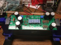
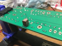
I had a little time yesterday and got the left hand board built up. Next step is to disassemble my F1 (temporarily) to use the chassis for testing the F3. The copper block on the back side of the amp board is to conduct heat from Q1 to the main heatsink.
I had a little time yesterday and got the left hand board built up. Next step is to disassemble my F1 (temporarily) to use the chassis for testing the F3. The copper block on the back side of the amp board is to conduct heat from Q1 to the main heatsink.
Attachments


I had a little time yesterday and got the left hand board built up. Next step is to disassemble my F1 (temporarily) to use the chassis for testing the F3. The copper block on the back side of the amp board is to conduct heat from Q1 to the main heatsink.
Perhaps a little side tracking but for anyone interested: The board holder pictured is currently being sold for 6.6 euros on Amazon DE, eligible for prime shipping. I have one. It's a steal and super useful for assembling boards like this en masse!

Thanks for a great project! Is there a BOM available as well?
I haven't put together a BOM yet, but I will create one after testing the boards is complete.
8-15-21 Update
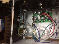
The left channel board has been powered up and for the most part all went well. No smoke, no drama. The bias came in lower than expected at 1.60A vs 1.65A so I need to dig into that. The surface mounted Q1 with copper bridge got up to ~ 45 deg C so that worked. Q2 was a bit hot at 65 deg C; I need to check to see that it has good contact with the heatsinks, although others in the F3 build thread have reported the same. I will post in the F3 build thread to work the bias and Q2 temperature questions.
The left channel board has been powered up and for the most part all went well. No smoke, no drama. The bias came in lower than expected at 1.60A vs 1.65A so I need to dig into that. The surface mounted Q1 with copper bridge got up to ~ 45 deg C so that worked. Q2 was a bit hot at 65 deg C; I need to check to see that it has good contact with the heatsinks, although others in the F3 build thread have reported the same. I will post in the F3 build thread to work the bias and Q2 temperature questions.
Attachments
Last edited:
Nice to see that it fit perfectly the 4U/300 🙂
Maybe better mica+grop for U2, as thought by Adason on F3 build thread?
Maybe better mica+grop for U2, as thought by Adason on F3 build thread?
The left channel board has been powered up and for the most part all went well. No smoke, no drama. The bias came in lower than expected at 1.60A vs 1.65A so I need to dig into that. The surface mounted Q1 with copper bridge got up to ~ 45 deg C so that worked. Q2 was a bit hot at 65 deg C; I need to check to see that it has good contact with the heatsinks, although others in the F3 build thread have reported the same. I will post in the F3 build thread to work the bias and Q2 temperature questions.
Same here, Q2 was the hottest. I replaced the keratherm insilator with mica and Q2 temp dropped ~15degC. All good now.
peppennino, the output caps should only be seeing 21V so caps rated for 25V should not have a problem.
Thanks Ed I had no idea that the performance of the Mica insulators was so much better, I have added them to my next parts order.
Thanks Ed I had no idea that the performance of the Mica insulators was so much better, I have added them to my next parts order.
Hi Chas. Can’t wait to build these - they’re looking great! Would you be willing to post the schematic you’re using for the amp board layout? If not, I just had a couple questions for clarification:
- on the main board, are the ‘to coupling cap -‘ and ‘to coupling cap +’ taking both ground and Signal to the coupling boards (thus taking output from coupling cap boards)? Or is it simply a loop back to the main board, and the ‘Out +’ terminal? I’m assuming it’s the latter, but wanted to double check. I may use some screw terminal electrolytics and film for output coupling, and was unclear of taking the filtered output from the caps or back to board was the way to go. Obviously ground would still come from the board (or perhaps PSU, as an option)
Thanks!
I haven't created a pretty schematic to post because it really just follows the F3 schematic, with the output caps (C1, C10, C8) on a separate board. The speaker output is on the main board because the output is needed for the feedback loop through R2 and C9, also it makes it easier to swap output caps to play with different values/types.
- Home
- Group Buys
- F3 Clone Board Set Group Buy