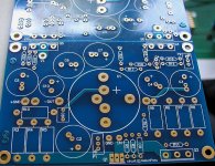
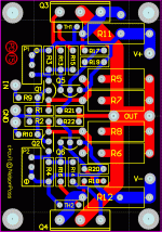
Peter Daniel said:It's still OK.
Money sent for an extra F3 PS board.
Thanks Peter.
Just added to Wiki 3 PSU, 1 F3 and 1F4. The 3 PSU is one for F3 and two for F4. Is that $75 all together?
Yes, it is correct. Payment info was posted here: http://www.diyaudio.com/forums/showthread.php?postid=1680605#post1680605
Re: Balanced F4
what are benefits of connection from post # 33 compared to dual channel stereo
why not connect single PS pcb with single pair pcb instead of connecting both + and - to different pair pcbs
what are benefits of connection from post # 33 compared to dual channel stereo
why not connect single PS pcb with single pair pcb instead of connecting both + and - to different pair pcbs
and some more psu boards
Peter - I will need 2 more psu boards - this time for the F2 - I assume that the F3 psu board will be applicable - if so thats another $30 to be paid.
Thanks
Alan
Peter - I will need 2 more psu boards - this time for the F2 - I assume that the F3 psu board will be applicable - if so thats another $30 to be paid.
Thanks
Alan
Re: Re: Balanced F4
Got it thanks.
Refering to this diagram: http://www.diyaudio.com/forums/attachment.php?s=&postid=1672598&stamp=1228160049 it is bridged configuration with two amp boards per channel providing more power as described here (page 7): http://www.firstwatt.com/downloads/f4_om.pdf
Each PS board in that diagram represent single voltage supply (+ or - ), so for symmetrical supply required by F4 amp you need two of those, connected to each amp board.
You can also use 4 of those PS boards (it's a PS board broken in half at scoring line), 2 per each amp board.
Got it thanks.
samoloko said:what are benefits of connection from post # 33 compared to dual channel stereo
why not connect single PS pcb with single pair pcb instead of connecting both + and - to different pair pcbs
Refering to this diagram: http://www.diyaudio.com/forums/attachment.php?s=&postid=1672598&stamp=1228160049 it is bridged configuration with two amp boards per channel providing more power as described here (page 7): http://www.firstwatt.com/downloads/f4_om.pdf
Each PS board in that diagram represent single voltage supply (+ or - ), so for symmetrical supply required by F4 amp you need two of those, connected to each amp board.
You can also use 4 of those PS boards (it's a PS board broken in half at scoring line), 2 per each amp board.
thx for explanation
could be achieved more power than 25 W from F5 connecting the upper way
if It can be done - are this going to be up to 100 W - has anybody test It
Is It correct that that way I need 2 F5 pcbs and 2 PS pcbs
could be achieved more power than 25 W from F5 connecting the upper way
if It can be done - are this going to be up to 100 W - has anybody test It
Is It correct that that way I need 2 F5 pcbs and 2 PS pcbs
In that way may I buy 5 PSU pcbs and 2 F5 pcbs from you
If so I have to pay you 7 x 15 USD and add 7 USD eventually for Insurance
If so I have to pay you 7 x 15 USD and add 7 USD eventually for Insurance
Yes no problem, payment info here: http://www.diyaudio.com/forums/showthread.php?postid=1684087#post1684087
I just realised there are a few more adjustment pots on the F3 compared to the ZV9.
Does anyone have the instructions for setting up the F3 correctly?
Does anyone have the instructions for setting up the F3 correctly?
- Status
- Not open for further replies.
- Home
- Group Buys
- F3 and F4 Clone PCB Reissue group buy, also F5 PCBs

