did you made test I wrote about in post #6 ?
Yes, I tried two different times, both prior to and after replacement of Q3, Q4, Q5 and Q6. My Fluke DMM didn't measure any current for either left or right side in the schematic in these tests.
how's that ?
you did something wrong
You're absolutely right. My bad in not configuring the dmm correct😱. Tested once more with disconnected Q1 and Q2.
Measured 1,72 A from drain Q4 and 1,70 A from drain Q3.
Last edited:
in that case , both CCS-es are OK
connect just one SSouth back in circuit , fiddle with P1 and report what you're getting (voltage vs. gnd) at that output side
re-check values of R15,R16 and P1
connect just one SSouth back in circuit , fiddle with P1 and report what you're getting (voltage vs. gnd) at that output side
re-check values of R15,R16 and P1
in that case , both CCS-es are OK
connect just one SSouth back in circuit , fiddle with P1 and report what you're getting (voltage vs. gnd) at that output side
re-check values of R15,R16 and P1
Ok, that's great. Re-checked values for R15, R16 and P1. They seem to be correct.
Reconnected Q2 first. Fiddling with P1, min/max drain voltage is 22,10 -> 22.15 V, i.e. only 50 mV difference.
Disconnected Q2 again, and connected Q1. Fiddling with P1, min/max drain voltage is 5,73 -> 7.93 V.
Do you think P1 needs replacement?
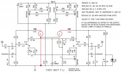
no , I think those SSouths are in question
from previous experience ,I know that they're hard to damage , but it's possible
pull them out and test - as any other mosfet , taking in account that gate voltage need to be in range of 1V5 , not 4V-oltish as fro IRFP
search at FW site for mosfet testing paper
however , it's wise to include little higher (in value) gate resistor and check voltage across it - to compare their gate currents
I have a friend , highly esteemed in world of professional photography , who succeeded in scorching few SSouths , while making an amp
however , if you are not having few bits and pieces for proper mosfet testing , I'll prepare another sch. edit , how to test them in circ ...... but tomorrow , must fly now .... 😉
no , I think those SSouths are in question
from previous experience ,I know that they're hard to damage , but it's possible
pull them out and test - as any other mosfet , taking in account that gate voltage need to be in range of 1V5 , not 4V-oltish as fro IRFP
search at FW site for mosfet testing paper
however , it's wise to include little higher (in value) gate resistor and check voltage across it - to compare their gate currents
I have a friend , highly esteemed in world of professional photography , who succeeded in scorching few SSouths , while making an amp
however , if you are not having few bits and pieces for proper mosfet testing , I'll prepare another sch. edit , how to test them in circ ...... but tomorrow , must fly now .... 😉
Thank you Zen Mod for your advice, I really appreciate your effort to help me out here.
I checked the mosfet testing paper you referred to. I don't know if I have the parts required to set up the mosfet test circuit as shown in the paper. However, I do have a spare pair of matched Semisouth R100's available, and I guess that replacing the ones currently in the circuit would be the easiest option?
....However, I do have a spare pair of matched Semisouth R100's available, and I guess that replacing the ones currently in the circuit would be the easiest option?
yup
Success!
I'm very happy to report that replacement of Q1 and Q2 made the circuit operate as intended. Quite a big DC offset of about 500mV though, but that's easily compensated by placing resistors in parallel with R5/R6. A very big thank you for invaluable help Zen Mod and generg.
I'm very happy to report that replacement of Q1 and Q2 made the circuit operate as intended. Quite a big DC offset of about 500mV though, but that's easily compensated by placing resistors in parallel with R5/R6. A very big thank you for invaluable help Zen Mod and generg.

Happy you got it with Zen Mods help!
how does it sound, i had only the IRF version….
Yes, I'm really happy now🙂
Well, the sound... I haven't built the IRFP version, so I'm not in position to compare the two. However, I have spent quite some time with my other F1J amp. The first that hits me every time I listen to it is the amazing clarity and transparency. I've also built a F2J, and switched back and forth between them. For me, the F1J is crisp and powerful, compared to the slightly more lush and laidback F2J. Until now, I have used them driving HifiMan HE-6 headphones, the latter being some current hungry beasts. Source is a PC with J River MC 20 and LynxTwo-B sound interface with balanced connections to the amp.
Thanks! And welcome in the switching back and forth club.... 🙂
Random noise from one of the channels
After some time using one of my two F1J's as a headphone amp, they're now both running in my 4 way active loudspeaker setup. The amps are driving midrange and tweeter horns (108 - 112 dB/W sensitivity). My setup consist of:
PC with LynxTwo sound interface -> F1J clone - > loudspeaker
I've noticed that one of the channels have a random crackling or sparkling noise, similar to that of an amplifier with a bad volume pot. I guess that with normal speaker sensitivity around 90 dB, this wouldn't be a big issue, but with horns the crackling/sparkling is quite annoying. The noise is most prominent when the amps are switched on from cold, but it's still there when they've reached operating temp. I've checked for bad solder connections, but haven't found any such yet. Anyone with similar experience, and suggestions on what to look for?
check for bad solder connections ........ again 
replace any passive elements being possibly heated too much during soldering
recheck bolts which tightens parts to heatsink
replace any passive elements being possibly heated too much during soldering
recheck bolts which tightens parts to heatsink
check for bad solder connections ........ again
replace any passive elements being possibly heated too much during soldering
recheck bolts which tightens parts to heatsink
Thanks ZM, I'll try that and report when done🙂
- Status
- Not open for further replies.
- Home
- Amplifiers
- Pass Labs
- F1J clone troubleshooting