A transformer capable of delivering 300 mA (with CT fullwave) will have an effective secondary resistance of about 25 Ohms per half. This will dissipate about 4.5W for B+ alone (heaters will add more, if supplied from the same transformer). And peak repetitive current will exceed 1A, more than double the EZ81's rating (450 mA RP). There are very few tube rectifiers that can take this. Now consider a SS full-wave bridge with an equivalent amount of iron and copper. No need for center-tap, equivalent secondaries can be connected in parallel for about 15 Ohms. 300 mA needs about 450 mA RMS, about 3W of transformer loss. And you've eliminated 20-30W of heater power, and 10-15W or so plate dissipation in rectifiers. A regulator will need a hefty heat sink, though, depending on voltage drop there.
You can use 1N4007 to provide a full-wave rectifier, but then insert all four EZ81 anodes in parallel to connect to the ss diode output node. The four EZ81 cathodes are connected in parallel and connect to the first filter capacitor. That is typically termed as 'bridging'. The peak rectified current pulse value is then split across four EZ81 diodes rather than just the commonly seen two parallel diode configuration. The effective voltage drop incurred by the EZ81 diodes is similarly reduced. The turn-off characteristic of the 'rectification' is still effectively dominated by the valve diodes characteristic, so you don't experience ss diode turn-off issues.
When designing a common PS a good starting point is to begin with the relationIs it possible to use a pair of EZ81 valves in parallel for a 300mA HT supply?
Cheers
Ian
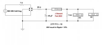
2*PI*f*Rl > 10
That will always result in ripple of less than 10%.
The requirement in the thread was not well defined. 300 mA, but at what voltage? Without knowing that there is no starting point. Later in the thread we see that this PS will power a professional mixer. So I assumed probably 300V B+. That is a One K load. Stuffing the numbers into the HP 67 I got 32 microF. So in the simulation we see 40 microF & sure enough the ripple is less than 10%. The over voltage is a place for the filtering, whether LC or a SS regulator.
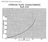
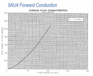
I thought the recommendation for a 5AU4 rectifier to be an excellent choice but can’t recall why that was rejected. For the paralleled EZ81/6CA4 the OP sez not enough data. Yet the data sheets clearly shew the forward drop. From that we can see the curve average to be ~72R. For a first pass I’d simply stuff something like 50R into the plate or cathode lead of each diode. Check that for safety & performance & run with it. Regulation of the required supply is not a problem, the load is all Class A stages.
All the calculations can be done on a 4-function calculator for those terrified by math.
What more does one need to design such a trivial PS? Since it is to be used in a piece of professional gear a better alternative may be to have the PS designed by a professional. This thread seems on the way to nowhere.
I'll add another quirk later!
Attachments

PSUD2 easily confirms the datasheet default setup for a 250-0-250V secondary with EZ81 full-wave and 50uF input filter and 160mAdc max load requiring a peak 500mA anode current (each anode conducts that peak pulse alternately).
EZ81 datasheet shows a diode on-voltage of 30V for a 280mA instantaneous level. PSUD2 has a 5AR4x2 diode model which can be used in a PSUD2 simulation to present a 30V diode on-voltage for 4x 280mA = 1.1A level, which is what happens in the bridged configuration with two EZ81 valves (four anodes in parallel).
Using the 5AR4x2 diode model in PSUD2 with 250-0-250V secondary, and an output dc load of 500mA (OP's target max) shows a peak 'diode' current of 1.2A (or 400mApk per anode) for a 150ohm transformer resistance, which is acceptably below the EZ81 per anode limit of 500mApk (or 2Apk for 4 anodes).
Even a 470uF filter cap can be used to suppress ripple. The transformer winding resistances, and any plate current sharing resistance, need to be confirmed to round out such a simulation.
So the outcome is that 2x EZ81 in bridging mode is quite a practical solution for up to 500mA dc load, assuming the OP can confirm operation with final part values using PSUD2. The only caveat imho is that bridging mode forces each EZ81 anode to conduct twice per mains cycle (rather than once in a typical full-wave rectifier), and so some thermal derating may be needed given each valve envelope could dissipate >100% of nominal max power.
Because right now I am just examining alternative rectifiers. Of course after that will come ripple reduction and stabilisation but they are separate matters. Is the board you pictured available anywhere?
Cheers
Ian
Hi
yes, I have done this project years ago and some pcb normally are available output voltage; the range is from 180 to 350 Vdc
There are 6 zeners to fix the value
Walter
Attachments

When designing a common PS a good starting point is to begin with the relation
2*PI*f*Rl > 10
That will always result in ripple of less than 10%.
The requirement in the thread was not well defined. 300 mA, but at what voltage? Without knowing that there is no starting point. Later in the thread we see that this PS will power a professional mixer. So I assumed probably 300V B+. That is a One K load. Stuffing the numbers into the HP 67 I got 32 microF. So in the simulation we see 40 microF & sure enough the ripple is less than 10%. The over voltage is a place for the filtering, whether LC or a SS regulator.
I think that probably confirms my own calculation. I got 90V pp which is not far from 30V rms which is 10% of 300V
snip
What more does one need to design such a trivial PS? Since it is to be used in a piece of professional gear a better alternative may be to have the PS designed by a professional. This thread seems on the way to nowhere.
I don't think it is too hard either but I have never used parallel tube rectifiers so I thought I would keep things simple by asking a very specific question so the thread would not become derailed and littered with senseless comments.
Cheers
Ian
Very interesting. Is there a mono version - I don't need stereo for my project.Hi
yes, I have done this project years ago and some pcb normally are available output voltage; the range is from 180 to 350 Vdc
There are 6 zeners to fix the value
Walter
Cheers
Ian
NoVery interesting. Is there a mono version - I don't need stereo for my project.
Cheers
Ian
only two way
There is another pcb more simply and a litlle bit less efficent
Walter
i think there is a typo or missing term in there somewhere. XWhen designing a common PS a good starting point is to begin with the relation
2*PI*f*Rl > 10
That will always result in ripple of less than 10%.
Edit: Starting from C.dV = i.dt and aiming for V/dV => 10 and noting that dt = 1/f , then I get:
C >= 10.i / f.V which gives, with f = 100, V=300 and i = 0.3 C = 100uF. That is assuming dV is peak to peak ripple.
Cheers
Ian
Last edited:
Ian, you are absolutely correct. That should readi think there is a typo or missing term in there somewhere. X
Edit: Starting from C.dV = i.dt and aiming for V/dV => 10 and noting that dt = 1/f , then I get:
C >= 10.i / f.V which gives, with f = 100, V=300 and i = 0.3 C = 100uF. That is assuming dV is peak to peak ripple.
Cheers
Ian
2*PI*f*C*Rl > 10
Most people would go somewhat farther to get the ripple down.
But the relation works OK if the following filter is LC. the choke energy storage into a reasonable size cap will fix all.
And results in lower RMS currents in the PT, something worth doing if the PT gets hot.
Not OK if the following filter is a SS or Toob regulator.
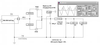
This is my 2nd pass at the PS in which we can study the effect of dissimilar plates of the rectifier operating on the same side of the PT HV winding. To do this the paralleled 6CA4 rectifier plates are driven from a common source generated by a full bridge SS rectifier. The 2R & 40R resisters represent the impedance of the supply PT.
There are no vacuum diodes in Electronic Workbench (EWB). But that is easily resolved, any triode can work as a diode simply by stuffing the EWB triode model with suitable numbers. For the 6CA4 I used plate volts of 30, plate current at 330 mA copied from the 6CA4 data sheet, Grid Volts at -0.1 & MU of 2. For the 6CA4 LO the plate current is simply changed to 320 mA.
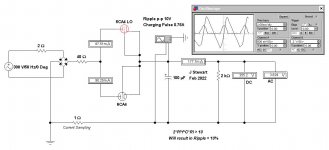
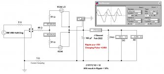
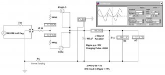
The first Sim shews both 6CA4 diodes to be equal. The 2nd introduces dissimilar diodes. The 3rd & 4th Sims shew that increasing the correction resistors forces similar loading of the diodes, But the effect of the PT impedance is a dominant factor until a significant correction resister of 100R is installed.
EWB was developed right here in Toronto. It was eventually bought by National Instruments (NI) & became the basis of their Multisim. Gradually the technology was moved to Texas.
If anyone knows a way to load spice files into EWB, pls let me know. I’ve been looking a long time & nothing yet.
There are no vacuum diodes in Electronic Workbench (EWB). But that is easily resolved, any triode can work as a diode simply by stuffing the EWB triode model with suitable numbers. For the 6CA4 I used plate volts of 30, plate current at 330 mA copied from the 6CA4 data sheet, Grid Volts at -0.1 & MU of 2. For the 6CA4 LO the plate current is simply changed to 320 mA.
The first Sim shews both 6CA4 diodes to be equal. The 2nd introduces dissimilar diodes. The 3rd & 4th Sims shew that increasing the correction resistors forces similar loading of the diodes, But the effect of the PT impedance is a dominant factor until a significant correction resister of 100R is installed.
EWB was developed right here in Toronto. It was eventually bought by National Instruments (NI) & became the basis of their Multisim. Gradually the technology was moved to Texas.
If anyone knows a way to load spice files into EWB, pls let me know. I’ve been looking a long time & nothing yet.
Attachments
Power Supply Ripple Sidebands
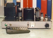
Here are a couple of spectrums showing PS Ripple Sidebands on program material. One with the CLC filter in the cct while the other is with the L shorted. The output is set at 2.5 Watts.
The amplifier is PPUL 6L6GCs, something I built two of around 1960. The CLC is 40 microF, 1.5H, 35 microF. The L is a Hammond 156R, small enough to fit inside the chassis. The B+ runs around 445V, thru a 5V4GA, but it was originally built for a 5AR4. The PT is a Hammond 273BZ. I have used SS octal rectifiers in this one with good results.
The amp is nominally 25 Watts.
The Spec A is a Pico Technolgy 16-bit ADC-216, so 96 db dynamic range is possible with care.
Attachments


Where does the 2 PI come from?Ian, you are absolutely correct. That should read
2*PI*f*C*Rl > 10
Cheers
Ian
The formula is usually printed using the Greek letter 'omega' which represents the 2*PI*f part.Where does the 2 PI come from?
Cheers
Ian
Far as I can see the DIY text formatting does not support Greek characters. That is a problem for 'micro' as well.
But I could be wrong.
Yes I understand omega and 2,PI.f but I don't think it applies for this calculation. Here is what MIT says on the subject:The formula is usually printed using the Greek letter 'omega' which represents the 2*PI*f part.
Far as I can see the DIY text formatting does not support Greek characters. That is a problem for 'micro' as well.
But I could be wrong.
https://ocw.mit.edu/courses/electri...-spring-2007/study-materials/ripple_volts.pdf
What this does not account for is the smoothing effect of the tube/transformer series resistance and the capacitor which of course does involve omega and which you simulation includes also.
Cheers
Ian
Last edited:
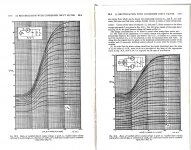
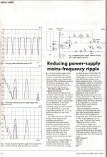
Indeed, but that part of RDH4 is not about ripple. As RDH says "in order that the direct voltage should not be closely dependent on the value of C. the value of wCRl must be on the right side of the knee of the appropriate curve of Fig30.x" And the knee of that graph is generally at about wCRl >= 10. This has nothing to do with choosing the value of C for a certain percentage ripple.This taken from RDH4. By choosing 2*PI*f*C*Rl > 10 we are well into good territory.
Page 1173 for full wave. In a text book the 2*PI*f part would be represented by the Greek letter 'omega'.
Cheers
Ian
The OH Schade complete report on rectifiers is part pf the Proceedings of the IRE, 1943 at this link-
https://worldradiohistory.com/Archive-IRE/40s/IRE-1943-07.pdf
Begins at p341 in the report but that is p55 of the document. There are many pages of product advertisements at the beginning of the document.
Worth a look for anyone who thinks they can design a PS.
https://worldradiohistory.com/Archive-IRE/40s/IRE-1943-07.pdf
Begins at p341 in the report but that is p55 of the document. There are many pages of product advertisements at the beginning of the document.
Worth a look for anyone who thinks they can design a PS.
Attachments

I didn't know you could make it this complicated. Schade's work is not new, but can be summarized much more concisely.anyone who thinks they can design a PS.
- Home
- Amplifiers
- Tubes / Valves
- EZ81 x 2 in parallel