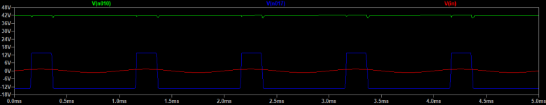
EZdump2 latch-up
Hey guyz, I simulated minek123's latest file and found that at an input overdrive of 1.3V or more, the circuit latches up to +40VDC. It seems that there is not enough positive feedback for the amount of bootstrap so the problem goes away if you increase R9 or R15. Seems like R9 could be 470 or R15 could be 33k to be safe.
I suspect I may find other things to say about this amp but I'll leave it to another post.
BTW, get well soon LV, DIYA needs you.
Attachments
The On-semi (and minek123) model for MJ21194 is seriously messed up. It saz the beta is BF=10000, but there must be more errors because fixing that parameter results in other problems. However the model for MJL21194, the plastic package version is fine. I suggest just using the MJL model.
Decrease the positive feedback R14 to 39k or more. See modified circuit for loop response.Any suggestions how this corrected?
Attachments
Hi Elvee, good to see you back in business! Hope you are doing better!
If you have a moment, could you please have a look at post #131 in this thread?
https://www.diyaudio.com/forums/solid-state/263065-ez-dump-dump-current-trying-14.html#post6318979
I haven't tried any fixes yet to get rid of this oscillation..
I guess most likely I need to adjust the value of one of small compensations caps..
Thanks!
I haven't a clue: I remember that the circuit was rather touchy, and would generate the kind of artefact you see when improperly stabilized, but in the end I got it reasonably stable.
I'll have a second look at my prototype one of these days.
Note that the parasitic capacitances from the bootstrapped section to the rest of the world play an important role, and some effects can be couter-intuitive: there are places where adding a stopper resistor or a compensation cap can have the opposite effect
I tried to use LTSPice to find out which caps/resistors may trigger this kind of oscillations. Two candidates:
1) C8 R19 - with low value for C8
2) R10/R26 - with low R values
1) C8 R19 - with low value for C8
2) R10/R26 - with low R values
Both are plausible, but C8 R19 imply something related to the GNFB, and most of the stability issues I encountered were just a second stage affair.
You can test the second stage in isolation by removing U2 and injecting the signal on the output pin.
The source has to be low impedance, 50 ohm for example or a short if you want to test the static stability. Don't leave this node open!
You can try to tweak R10 R26 (and C9 C10) in the real world; they certainly have some kind of influence
I'm trying now to make my model work with actual transistors I used.
So far it doesn't work at all in spice; my actual build at least worked to some degree.
ASC attached.
One the problems - idle current for output devices is way too high.
This does not correspond to the actual build..
So far it doesn't work at all in spice; my actual build at least worked to some degree.
ASC attached.
One the problems - idle current for output devices is way too high.
This does not correspond to the actual build..
Attachments
Last edited:
In sim, the circuit is latched-up because with the 45V rails, the CM range of the second stage is exceeded (it is limited by the 30V supply zener).
As a result, the output is stuck to the - rail.
As a quick fix (more a theoretical proof in fact), I changed the 30V diode for a 51V one, and it seems to behave more normally.
In reality, 51V would be too much for most opamps; a more reasonable solution for high voltages would be the recalculation of the FB resistors ratio for the second stage, to remain within the 30V limit.
PS: I made a little room in my inbox, if you need to send me a message
Attachments
Thanks Elvee!
But why this happens only with KSA992/KSC1845?
If I replace Q7/Q8 with BC transistors, everything works fine with 30V Zener...
I thought Q7/Q8 can be pretty much anything..
But why this happens only with KSA992/KSC1845?
If I replace Q7/Q8 with BC transistors, everything works fine with 30V Zener...
I thought Q7/Q8 can be pretty much anything..
It's just a sim quirk: no need to dig deeper, but you have to heed the warning: in real life, it could very well happen for some types of opamps.
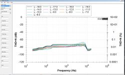
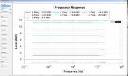
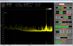
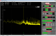
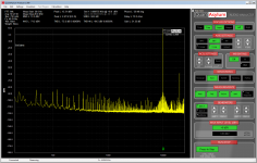
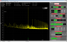
Here are some measurements of my active current dump amp build,
done with qa401 audio analyzer.
Thd from 0.037% at 3W to 0.049 at 50W.
Obviously they slightly differ from the sim (unfortunately for the worse).
done with qa401 audio analyzer.
Thd from 0.037% at 3W to 0.049 at 50W.
Obviously they slightly differ from the sim (unfortunately for the worse).
Attachments
Last edited:
It is instructive, but puzzling: one would think that the large loop gain provided by the opamps would annihilate the distortion, but it doesn't.
The bridge balance must be good, otherwise the low-level THD would climb.
I remember trying to measure the THD of another composite amplifier (not a current-dumping one), but I didn't succeed, even with combined filtering-subtraction methods: it was below the ppm
The bridge balance must be good, otherwise the low-level THD would climb.
I remember trying to measure the THD of another composite amplifier (not a current-dumping one), but I didn't succeed, even with combined filtering-subtraction methods: it was below the ppm
Elvee, I will make another attempt to build one of the 'passive current dump' designs of yours.
1st build didn't work well, maybe 2nd time will be a charm 🙂
To refresh our memory, here is the schematic:

I have few questions:
1) Caps added between balance pins (1 and 5) and +Vee: should be added to 1st or 2nd or both op-amps?
2) 10nF values will be OK? Or smaller?
3) R16, R13, C7 should go to input ground or dirty ground? My guess would be 'input ground'...
1st build didn't work well, maybe 2nd time will be a charm 🙂
To refresh our memory, here is the schematic:
I have few questions:
1) Caps added between balance pins (1 and 5) and +Vee: should be added to 1st or 2nd or both op-amps?
2) 10nF values will be OK? Or smaller?
3) R16, R13, C7 should go to input ground or dirty ground? My guess would be 'input ground'...
Attachments
I don't remember the purpose of these caps, and I don't see them in any of the schematics. Can you provide a pointer?1) Caps added between balance pins (1 and 5) and +Vee: should be added to 1st or 2nd or both op-amps?
No idea at the moment2) 10nF values will be OK? Or smaller?
They are referred to the "driver" stage, thus belong more to the output (dirty) side3) R16, R13, C7 should go to input ground or dirty ground? My guess would be 'input ground'...
Elvee,
See post #96
You call them 'balance bypass capacitors'.
See post #96
I have made serious, comprehensive tests to understand the (marginal) stability issues.
I came to a conclusion: they originate mainly from two elements: the floating second-stage amplifier, and the diamond buffer/base-spreader, in particular the collectors connection.
The second stage is vulnerable, because the whole of the ambient world is "hot": as it sits at ~the output potential, each of its nodes sees a parasitic capacitance connected to a 100Vpp source, and even with femtofarads of capacitance, it is sufficient to cause an unwanted ingress.
The nodes include the inputs, of course...
You call them 'balance bypass capacitors'.
Thanks for the reminder: now it is coming back. The OS pins can act as inputs, but this is generally not an issue: just keep high level tracks away from them.
With a floating stage, everything is high level wrt. to the chip, including the OS pins, meaning they have to be protected one way or another. Shorting them together in AC with a cap is probably the easiest option, and it doesn't alter the DC conditions
With a floating stage, everything is high level wrt. to the chip, including the OS pins, meaning they have to be protected one way or another. Shorting them together in AC with a cap is probably the easiest option, and it doesn't alter the DC conditions
Thanks Elvee, so this could be done on 1st op-amp or both?
In one of the posts you mentioned values of 10nF or 22nF, so that solved.
In one of the posts you mentioned values of 10nF or 22nF, so that solved.
- Home
- Amplifiers
- Solid State
- EZ-Dump: dump your current without really trying