Yes, but JLH did not have push pull output.
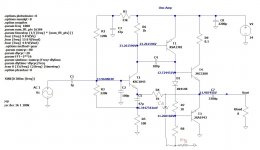
One thing I noticed with this amp that is unique: despite having output coupling cap, there is a slight 500mV DC offset due to the connection from the base of the PNP to the output after the cap.
This offset is not a good thing as voice coil will heat up a bit.
JLH A-class amp is also with push pull output ,
to avoid that output DC offset bias network need to be slightly modified by adding one more cap(C6) and one more resistor (R10),
this simple amp will sonicaly outperform many other solid state amps for sure because of his very specific THD spectrum .
Attachments
JLH A-class amp is also with push pull output
That's strange as I thought that the JLH 1969 had two NPN's for output? I guess I should have said complementary push-pull.
http://www.keith-snook.info/wireles...ss-World-1969/Simple Class A Amplifier - .pdf
Last edited:
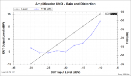
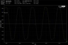
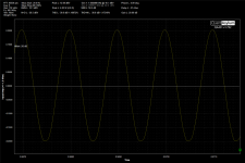
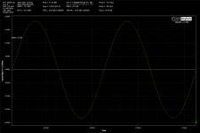
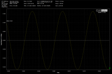
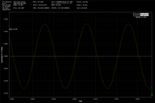
Output wave format from 1.65W to 5.23W:
In this test, I was increasing the input in 1dBV steps, from -12 to -6dBV.
In this test, I was increasing the input in 1dBV steps, from -12 to -6dBV.
Attachments


maybe this is safer than UNO?
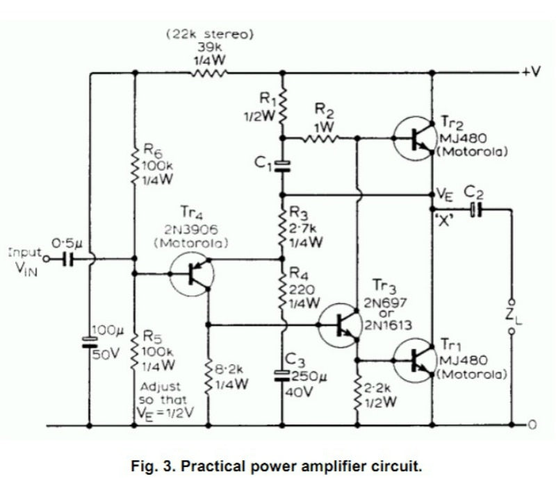
It's a Philips/Valvo/MBLE/Mullard/RTC/Elcoma etc. app note, so safe and problem-free like the proverbial Volvo (or a Japanese car, if you prefer)
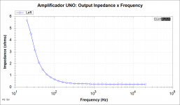
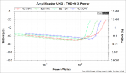
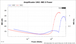
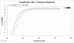
Results are quite decent, and typical of such an amplifier.That's the test results:
More problematic are the simplifications, like dispensing with emitter resistors: they look like a good idea, until you run into real problems
I wonder if there would be much to gain by fitting more suitable types of power transistor to such ~15W amplifiers as this Philips design. In other words, if we already have something like FJPF5200/1943 or even D44H11/45H11 which are often classed as audio transistors?
Last edited:
Attachments
Last edited:
I have built some amps with these, even a minified JLH'69 - these are a little faster than originally specced devices, so there must be some compensation added. Otherwise probably good for something up to 10-something watts of class-AB......
or even D44H11/45H11 which are often classed as audio transistors?
...
But the above "black devil" amp is a good example of german enginierung: how to squeeze 50W out of a topology initially layed out for ~5W amps ...
If 'Mericans were at it, we would probably look at some double-digit-transistor topology ...
That's the test results:
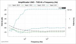
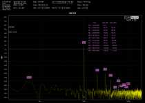
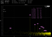
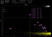
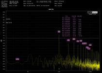
Very extensive test results but would be helpful to see FFT freq magnitude vs frequency to see the nature of the HD.
...I thought that the JLH 1969 had two NPN's for output?....
And tons of push-pull tube-amps have two n-type 6L6 or whatever. Mostly transformer-yoked, but totem-pole push-pull n-type can be found, in glass as in TO3.
You are indeed confusing with "complementary".
Sure, I will print that next time.Very extensive test results but would be helpful to see FFT freq magnitude vs frequency to see the nature of the HD.
FFT by frequency
Very extensive test results but would be helpful to see FFT freq magnitude vs frequency to see the nature of the HD.
Attachments

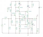
I used this with mosfets and op amp dc servo. worked great for many years. 125 wpc @ 4 ohms with 33v rails
I used this with mosfets and op amp dc servo. worked great for many years. 125 wpc @ 4 ohms with 33v rails
Would you have a schematic?
> 40mA or so DC through the speaker? That's about 300mV offset voltage for an 8 ohm speaker.
Yeah, not top-shelf performance.
But it is only 5% of the peak output, so speaker excursion is hardly used-up. 1/10th Watt DC dissipation should not bother the 2+ Watt speaker needed. And it IS just 4 transistors, 3 stages. It seems a tolerable trade-off.
Yeah, not top-shelf performance.
But it is only 5% of the peak output, so speaker excursion is hardly used-up. 1/10th Watt DC dissipation should not bother the 2+ Watt speaker needed. And it IS just 4 transistors, 3 stages. It seems a tolerable trade-off.
- Home
- Amplifiers
- Solid State
- Extremely simple amplifier (4 transistors) with low THD.