I'm studying some simple tube amps and specifically the P1-eX from ax84. The schematic shows a B+ of 388V but uses a power transformer with a 275-0-275 secondary and a two diode full wave rectifier. My understanding is that in order to have a B+ of 388V right after the rectifier, you would need to have a 388-0-388 secondary. Am I getting something wrong? Sorry if this is an extremely beginner question. 😕
Here's the schematic:
http://ax84.com/static/p1x/AX84_P1x_101004.pdf
Here's the schematic:
http://ax84.com/static/p1x/AX84_P1x_101004.pdf
If you've learned the fundamentals that are first, and mandaory in electronics, you'd understand the reasoning behind such things.
You have to have the "key" and gasoline in the tank before attempting to start the car and go someplace.
Right?
Do some reading of RMS voltage, Peak voltage, and you'll find plenty of answers to your questions.
Specifically, the value of 1.414 will become clear.
You have to have the "key" and gasoline in the tank before attempting to start the car and go someplace.
Right?
Do some reading of RMS voltage, Peak voltage, and you'll find plenty of answers to your questions.
Specifically, the value of 1.414 will become clear.
TubeN00b,
The UF4007 diode drop is about 0.7V.
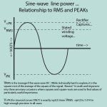
The Peak voltage of a Sine Wave is Root(2) = 1.414 times the Sine Wave RMS voltage.
275Vrms x 1.414 = 388.85VDC
388.85V - 0.7V diode drop = 388.15V Close enough?
There are other, but smaller factors, so you may get a little less than 388V, or you may get a little more than 388V.
Examples:
Your Mains voltage varies from 117V to 123V (mine does).
Your Mains voltage is a slightly clipped Sine Wave (3rd Harmonic distortion). That means the Peak voltage is slightly less than 1.414 x the AC rms voltage. 3% clipping distortion is about 3% less peak voltage.
The DCRs (DC Resistance) of the transformer primary and secondary are a little bit higher than they should be. AC current through the DCR of a winding = a voltage drop (current times voltage). A cap input supply (like in the schematic you posted) has the highest peak currents (highest voltage drop due to DCR). Transformers are often rated for a resistive load (currents are Sine Wave shaped, not shaped like rectifier(s) feeding capacitor input filters.
Pretty much "enough" for most, but not all of the factors involved.
wiseoldtech beat me to the punch. In 1956, I went to the library, and devoured the basic electronics Theory portions of a 1956 ARRL Radio Amateur's Handbook. Library (no online ordering then). The current issues are still an excellent self-teaching and reference book. Search online, and purchase one, with study, you will suddenly be way ahead of many many others.
When I went to a radio amateur's swap meet, I purchased several older used copies of the handbook for my co-workers (I like those books).
The UF4007 diode drop is about 0.7V.
The Peak voltage of a Sine Wave is Root(2) = 1.414 times the Sine Wave RMS voltage.
275Vrms x 1.414 = 388.85VDC
388.85V - 0.7V diode drop = 388.15V Close enough?
There are other, but smaller factors, so you may get a little less than 388V, or you may get a little more than 388V.
Examples:
Your Mains voltage varies from 117V to 123V (mine does).
Your Mains voltage is a slightly clipped Sine Wave (3rd Harmonic distortion). That means the Peak voltage is slightly less than 1.414 x the AC rms voltage. 3% clipping distortion is about 3% less peak voltage.
The DCRs (DC Resistance) of the transformer primary and secondary are a little bit higher than they should be. AC current through the DCR of a winding = a voltage drop (current times voltage). A cap input supply (like in the schematic you posted) has the highest peak currents (highest voltage drop due to DCR). Transformers are often rated for a resistive load (currents are Sine Wave shaped, not shaped like rectifier(s) feeding capacitor input filters.
Pretty much "enough" for most, but not all of the factors involved.
wiseoldtech beat me to the punch. In 1956, I went to the library, and devoured the basic electronics Theory portions of a 1956 ARRL Radio Amateur's Handbook. Library (no online ordering then). The current issues are still an excellent self-teaching and reference book. Search online, and purchase one, with study, you will suddenly be way ahead of many many others.
When I went to a radio amateur's swap meet, I purchased several older used copies of the handbook for my co-workers (I like those books).
Last edited:
The simple book equation for full-wave rectification is to take the RMS input and take the PEAK....which is 1.414 ...
275 * 1.414 is your 388V, this would be the voltage at the first cap when the circuit is unloaed.... Amp on Stand-By drawing no load.... However the 275V AC RMS number is speced what you would get when loaded @ 90mA ...
Between copper loss and core loss typical Hammond PT is about 92% efficient...
Once you know more details of the circuit and transformer it is possible to calculate the voltages very accurately...
The schematic shows a B+ of 388V but uses a power transformer with a 275-0-275 secondary and a two diode full wave rectifier. My understanding is that in order to have a B+ of 388V right after the rectifier, you would need to have a 388-0-388 secondary. Am I getting something wrong?
Use 275-0-275 transformer. Here a link to a very good article on how to do this.
The Valve Wizard
Thanks for all the replies. My understanding now is that the B+ is measured at 388V (Vpp) and the transformer secondary gives 275V (Vrms), is that correct?
Use 275-0-275 transformer. Here a link to a very good article on how to do this. The Valve Wizard
The simplistic basic 1.414*RMS is ideal and for unloaded situations... There are many things to consider when the circuit is loaded... For example, the conduction angle will vary depending on input cap value thus will change the voltage drops differently...
TubeN00b, Your posted schematic is for a guitar amp. It uses lots of shielded cables inside the amp. Those are there to prevent hum pickup within the amp. But . . .those are low pass filters. The higher frequencies are removed. There are also other circuit details that remove the higher frequencies. That may be OK for a guitar amp. If you want a Hi Fi amplifier for general music playback, you need to look at other schematics. Some Hi Fi schematics will look quite similar to the guitar schematic.
And the Hi Fi schematics will be as simple, or even simpler. But they have paid attention to circuit details that give them a wider frequency range needed for Hi Fi. I only build Hi Fi amps, not Guitar amps. But if I was to start with your schematic and build a Guitar amp, I would make some changes (for some Guitarists it would be for the better, and for some other Guitarists it would be for the worse). Good luck building either the Guitar amp, or Hi Fi amp of your choice.
Let us know which you are wanting to build.
I am fully aware that it is a guitar amplifier, that is what I want to build. What would you do differently? By the way, since this is my first "serious" electronics project, I am thinking about removing the tone stack entirely, for simplicity's sake. Would that necessitate any further modifications to the design? Please keep in mind that I don't have particularly high demands for the amp's sound quality. For now, I just wanna understand the basics and build something simple that works.
Lots of great advice from the old Tube Masters of DIYAudio, for sure. But to be crystal clear in a memorable sort of way…
Hopefully that helps.
GoatGuy
Hopefully that helps.
GoatGuy
Attachments
Last edited:
With regard to your comment № 10, removing the tone 'stack', yes, this might be worthwhile, for simplicity. The amplifier as shown will have quite high gain — the first and second tube sections deliver about 25× to 30× each, for 600× to 900× of total gain. While this sounds high, note that it is driving the tone adjustment 'stack', whose job it is apart from modifying the tone, is to suck down some of that gain before the final pentode.
One of the little thoughts I have is that instead of a 'tone' setup, over time as the amplifier matures, you could implement 'fuzz' and other guitar-friendly amp circuits in there. Its always a question of 'where do you put them' (in terms of schematic, not physical placement!) … but ideally between the first triode and second probably makes most sense. … the possibilities are endless!
Good Luck.
The design is 'bog standard', and ought to serve your purposes well.
GoatGuy ✓
If someone had one of these built to spec, and you can listen to one, that would be nice.
If I made any changes: I would use a 1k grid stopper (10k if 1k was not enough effect) between the shielded cable input, and the input grid (reduce the possibility of RF interference).
You should not have problems with stability if you are careful about wiring layout (there is no negative feedback). Keep input stage away from output stage, and input stage away from power supply. Proper grounding techniques should prevent hum. Make the first 2 filter caps have their own ground loop (center tap connected to the first filter cap negative lead, then connect that to the 2nd cap negative, and Then from there to a central ground point, which connects to the chassis at that point. Make the input connector float from the chassis, and connect that connector shell to the bottom of the input tube cathode resistor/capacitor combo. Then connect that to the central ground point.
With an EL34 in pentode mode, I might change the potentiometer that drives the EL34 control grid to 500k Ohms. (a little more reliability, prevent possible thermal runaway of the output tube). That will reduce the total gain a little, and will change the frequency response of the tone stack slightly.
TubeNoob,
On second thought, since this is a Guitar amp, and will have a fairly long cord from the guitar to the amp (compared to a Hi Fi amp with a 2 foot cord from a preamp to an amp) . . . You probably will have to ground the input connector shell where it enters the chassis.
A steel chassis is tough and stiff (advantage). Disadvantages: A steel chassis is hard to cut and drill (use a company that can do a lazer cut?). And except for Some kinds of stainless steel, they are magnetic. Magnetic chassis will couple hum from the power transformer to the output transformer.
The output transformer and power transformer are close to each other on the chassis. Make sure that the coils of those two are at right angles to each other. That will reduce the coupling of hum through the air.
An aluminum chassis is not as rigid/tough (disadvantage). Advantage: An aluminum chassis will not conduct magnetic hum interference like a steel chassis does. And aluminum is easier to cut, drill, etc.
...guitar amp. ...It uses lots of shielded cables . . .those are low pass filters. ...
There is much more gain than we usually find in Hi-Fi rigs. Even a simple amp like this is prone to supersonic squeal. I was startled how sensitive a Champ is to tone-pot wire routing.
Gain from first grid to last plate is 10,000 - compare to Hi-Fi with Gv=100 in phono, Gv=10 in line-stage, Gv=20 in power amp. While that looks to add-up to more gain (needle is weaker than axe), at the top of the audio band the phono gain is only 20, so supersonic squeal is more liable in guitar than Hi-Fi.
Also: it's all relative. The two coax runs are 4 and 6 inches. Taking 30pFd/foot, the long one is 15pFd. The grid of a gain-triode is 100pFd. The power-pentode's C is less, but another 15pFd is no big deal.
OTOH you do NOT want "full range" on e-guitar. The overtones of a tight naked steel string are not harmonics, and get increasingly dissonant a few octaves up. (Emphasized by amplifier distortion overtones being exact harmonics.) While we normally use the too-big speaker to sharp high-cut at 5KHz, and Fender made a tone by allowing rising amplifier response 1KHz-5KHz, we are quite OK with an amp that falls by 20KHz.
I've built the P1-eX as well as various other guitar amps. The tone stack doesn't add a much complexity to the build but does afford considerable tonal flexibility. Leaving it out will reduce costs (good pots are expensive), but you'll end up putting an EQ pedal in front of it, I reckon. If you haven't read the AX84 P1-eX theory doc, then I recommend that as a good start for answering questions about why workings of that amp.
Stph
Stph
For Hi-Fi, we want the amplifier to accurately reproduce all the treble in the input signal, so we want a flat frequency response extending beyond the human ear's capability (20 kHz or a bit more.)There are also other circuit details that remove the higher frequencies. That may be OK for a guitar amp.
For electric guitar, we want the instrument to sound good. "Good" is subjective to a considerable degree, but it's fair to say that the bare instrument does not sound good to the vast majority of people in this decade. (It may have been different in 1950, when the instrument was new to most people and interesting for its novelty.)
Plug your guitar (properly buffered) into a good Hi-Fi system, and it will typically sound harsh, cold, thin. Turn up the volume, and it will usually start to sound extremely unpleasant - the harsh attack at the beginning of each note feels like being stabbed in the ears.
A good guitar amp is designed to remove these unpleasant sonic characteristics. It does this by intentionally distorting the guitar signal in a variety of ways.
Harsh treble frequencies are deliberately filtered out (mostly by the guitar speaker). Deep boomy bass (80 Hz - 150 Hz) may also be filtered out to produce a more balanced sound. Some nonlinear distortion may be used to "squash" those harsh attacks at the beginning of each note. Starting in the 1960s, large amounts of harmonic distortion are often added, to give the guitar growl and bite and sustain. At this point, there is very little resemblance between the signal going into the guitar amp, and the signal coming out!
Also, as PRR said, midrange frequencies might deliberately be notched out (for some reason, many e-guitars sound sweeter and less harsh if you notch out some frequencies around 800 Hz.)
So a good Hi-Fi amp is a bad electric guitar amp, and a good electric guitar amp is a bad Hi-Fi amp. What's good for one is very often bad for the other.
This is very counter-intuitive to those of us who have spent a lot of years learning about audio. Audio amps are very much alike for 99% of uses (Hi-Fi, P.A., TV, cellphone, MP3 player). The huge exception is e-guitar, where normal audio engineering rules simply do not apply.
I made a lot of bad DIY guitar amps because I didn't understand this. In those pre-Internet days, such information was not easy to come by, so I used what I knew about Hi-Fi. And that resulted in bad-sounding guitar amps!
I'm attaching an image of the frequency response of an Eminence Legend 1028k guitar speaker, with some annotations I added. The speaker itself is incapable of reproducing frequencies below 60 Hz or above 6 kHz - and that is on-axis - right in front of the speaker.
Installed in a typical guitar cab, some of the bass below 100 Hz will be filtered out. Off-axis, where we usually listen to e-guitar, high frequencies will be even more significantly filtered out - I suspect there is not much above three or four kilohertz to be heard in a typical off-axis listening position.
-Gnobuddy
Attachments
Gnobuddy,
Yes. Agreed.
And I know about electric guitar frequency responses, lead and bass. I have done spectral studies on them, including real time analyzers with waterfall color spectrograms, and other facilities.
I remember one lead guitar recording that had tremendous downward high frequency slope. It had fast low pass filtering, then a brick wall filter, absolutely no high frequencies. A high frequency tone would have only the very lowest harmonic numbers, of any.
As to PA systems, it depends on whether they are designed for voice or to play music too. Some are closer to old standards for old communication systems.
You ought to hear voice announcements over a US Naval Destroyer that had the Keel laid in 1943.
When early digital cell phone base stations could only handle extremely low data rates, some very major compromises were made. I worked with one of the engineers who designed one of the most intelligent voice "squashers" for cell phones. It worked fairly well for american english of average accent, but not so good for certain locations in the US due to accents. For foreign languages, it was terrible to un-intelligable. It was further from Hi Fi than any guitar amplifier ever 'thought of being'.
What is very funny is starting with a guitar amplifier with the rolled off high frequencies. But then a player gets the gain turned all the way up, wails on his guitar, almost breaks the strings, and completely clips the amplifier. Now, the power of the amp doubles, and 50% of it is odd order harmonics. The speaker becomes the only attenuator of those amplifier generated harmonics. If the clipping has uneven times of the positive and negative excursions, then in addition to odd harmonics, there are very strong even harmonics too. And at this level, the speaker cone is just as likely in break-up mode, generating its own harmonics. Those may not all be on axis, because of the break-up angles of the non-pistonic cone.
Almost 50 years of spectral analysis can teach a lot.
Last edited:
If you ever feel like sharing some of what you learned, I for one would love to learn more. 🙂...electric guitar frequency responses...done spectral studies on them...
It seems that for some eighty years now, tube guitar amplifiers have been designed primarily by ear. I think the possibilities are ripe for using some relatively modern measurement techniques to supplement human ears.
Randy Bachman (guitarist for Bachman Turner Overdrive) was famous for his long, sustained, cello-like solo guitar parts. About all I can find out is that he started out with a Fender Champ used as a preamp between his guitar and his main guitar amp, and later replaced it with a Herzog, basically a Champ with a dummy load, which was custom-built for him by "Gar" Gillies of Garnet amps....one lead guitar recording...tremendous downward high frequency slope...absolutely no high frequencies.
The thing is, a Champ is a fairly harsh beast on its own, and cascading that in-line with a full guitar amp should have produced a harsh, buzzy tone. But that's not what we hear on the records at all.
I found a reference that stated that Bachman couldn't get the sounds he wanted from his Herzog + big Fender amp, and Gar then built him a custom tube guitar amp using Heathkit parts. And with that amp plus his Herzog, Bachman finally got the cello-like guitar tones he'd been searching for.
How did Gar get those tones out of his amp? I think a lot of carefully designed treble filtering is what made the difference. The story goes that it took weeks of experimentation to get it to sound right.
Wouldn't it be nice if we could run a spectral analysis on a recording of one of Bachman's solos, subtract the spectrum of a similar-vintage recording of the same guitar played through some other amp of known frequency response, and work out roughly what sort of filter response Gar Gillies came up with to create those cello-like tones? 🙂
I may have over-simplified in the interests of brevity. But I think it's fair to say that most PA systems at least attempt to avoid unnecessary harmonic distortion, while modern guitar amps attempt to deliberately create it!As to PA systems, it depends on whether they are designed for voice or to play music too. Some are closer to old standards for old communication systems.
Do they sound worse than the folded sheet-metal horn speaker on the roof of the Blues Brother's "Bluesmobile"? 😀You ought to hear voice announcements over a US Naval Destroyer that had the Keel laid in 1943.
I've heard those folded-horn compression-driver speakers on trips to other countries, and they sound worse than telephones from the 1970s. No bass at all, no treble above a few khz, and a series of big honky / shouty / screechy resonances throughout the midrange. 🙂
My 85-year-old mother in law got a new cellphone recently. She has a weak voice, and if she allows the phone to move more than an inch from her mouth, her voice turns into garbled and completely unintelligible nonsense....voice "squashers" for cell phones...
That said, the audio amplifier chip in the cellphone isn't designed to distort on purpose...it's probably the software audio codec doing that, possibly as a result of attempting to cancel the ambient noise.
This is something that only dawned on me a few years ago, when I first started thinking about improving the treble dispersion of a guitar amp by using a crossover network and some sort of smaller driver to take over from the big 12" or 10" speaker above, say, 500 Hz....completely clips the amplifier...the speaker becomes the only attenuator of those amplifier generated harmonics.
Once could certainly use a traditional passive LC network to filter off those high frequencies, but actual guitar speakers seem to roll off at about 24 dB/octave (4th order) starting at around 3.5 kHz, which would make for a fairly complex LC network.
Worse, there is the slow rise in frequency response of as much as 10 dB between roughly 300 Hz to 3.5 kHz. That comes from the guitar speaker itself, and using two speakers with a crossover network would make it quite difficult to generate that sort of frequency response.
(I haven't tried crossing over to a much more sensitive smaller driver, which might serve to generate something that sounds similar to the slowly rising response of a typical guitar speaker.)
Considering these complexities, it becomes clear why guitar amp manufacturers have mostly stayed with the "guitar speaker as filter" approach, except for some expensive solid-state modelling amps that use an electronic cab-emulation filter, a flat-response speaker, and vast amounts of output power to generate the SPL needed even without the speaker doing the heavy lifting for you.
-Gnobuddy
- Status
- Not open for further replies.
- Home
- Live Sound
- Instruments and Amps
- (extremely) Noob question about power transformer