Paul, do not do stupid, the image is in place, you give a link to the page, I put a link to the image on the page. Paul, do not write what is not true, no original placement is not misused.
English please, you're not making sense at all.
It was enough to measure the wrong voltage T1 and T2 and not add anything unnecessarily.
That's it.
Federmann: I measured voltage across R5 and R6 on Bahdan´s boards after building, general. It was 0,22 V (0,18 V) and 0,21 V (0,17 V). Is it correct? 😉
Federmann: I measured voltage across R5 and R6 on Bahdan´s boards after building, general. It was 0,22 V (0,18 V) and 0,21 V (0,17 V). Is it correct? 😉
voltage across R12 and R14=?
voltage across R13 and R15=?
(UCT1=? UCT2=?)
Federmann: I measured voltage across R5 and R6 on Bahdan´s boards after building, general. It was 0,22 V (0,18 V) and 0,21 V (0,17 V). Is it correct? 😉
Voltage across R5 and R6 is shorted L1. The measurement is unnecessary.
Voltage across R5 and R6 is shorted L1. The measurement is unnecessary.
I am not sure if anyone here understands what you are trying to say.
I am not sure if anyone here understands what you are trying to say.
The real question is whether we want to?
I welcome input and feedback, afterall by entertaining other views, ideas and perspectives we learn, but in order to be able to digest it it needs to be in a form that makes sense, a spree of single line posts referring to who knows what isn't the most constructive way to get a point across.
So Federmann please be concise, to the point and as detailed as possible when providing input and/or feedback otherwise your effort is wasted, as is ours.
Have you seen this paper on a bias method which reduces AB switching distortion? AES preprint number 1683 (D-4) Oct 1980:
"Quasi-Class A/Improved Class AB Bias Loop" by G.Dodson of JBL
Concept from AES paper:
View attachment OPS Bias.pdf
THx-RNMarsh
"Quasi-Class A/Improved Class AB Bias Loop" by G.Dodson of JBL
Concept from AES paper:
View attachment OPS Bias.pdf
THx-RNMarsh
So here's my build so far...
Amplificateur ExtremA Classe-A 100W
Wanted to finish it a long time ago but been extremely busy.
The chassis will be like a tank! Everything will get anodized
Ciao!
Do
Amplificateur ExtremA Classe-A 100W
Wanted to finish it a long time ago but been extremely busy.
The chassis will be like a tank! Everything will get anodized
Ciao!
Do
?? What the perfect amp is wrong?
Nice- that only took 5 years after mine was built...with your incorrect guide and insults to the measurements.
Thanks for spotting that, you're absolutely correct. Corrected stuffing guide is attached below.
Nice- that only took 5 years after mine was built...with your incorrect guide and insults to the measurements.
I need to know if anyone has experienced oscillation with the amp. I'm not ready to call this oscillation until I bring it to someone with an oscilloscope to check but here's my issue..
On the high-current supply I have +/-24.5Vdc and on the regulated low-current supply I have +/-29.75Vdc. Amplifier has been assembled with component values from the BoM and I have also done all the latest recommended changes below
***Update 10-12-2014: Updated stuffing guide***
The silkscreen for the amplifier PCB contains an error where the labeling of L1/R6 is swapped.
If you've already built the amplifier, please swap L1/R6 around as the amplifier will see a large(r) DC offset and reduced performance due to this error.
***Update 01-12-2014: parts value change***
With a simple parts value change the ExtremA amplifier sees an improvement in slew-rate, step response and overall stability, so it is recommended making these changes. There's four capacitors that need to be changed:
C1/C2 = 68pF - COG or NPO - 5mm pitch (Vishay NP0 ceramic)
C4/C9 = 220pF - film capacitor, polypropylene or polyester - 5mm pitch (WIMA FKP2)
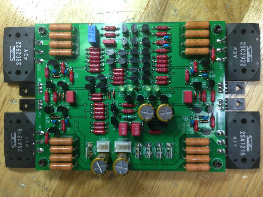
The emitter resistors are metal film 1 Ohm 3W 1%. The amplifier powers on no problem but the Sanken become extremely hot in 5-10 minutes (80 Celcius) and the 4x 1 Ohm resistors on the Sanken emitter become really hot as well (+/- 80 Celcius as well and cause drifting). I can adjust the DC offset without any problem and music plays as well.
My question is why those resistors R38-R45 and R53-R60 become sooo hot? Recommended is 2 Watts and I have 3 Watts. Is the bias current too high? I'm estimating 2.75A.
But I do have some serious metal shunk on these...
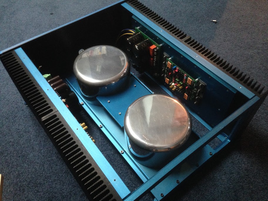
I don't know if you can see it but aside the heatsink, there's a 1/2" aluminum plate. As you can see below on my early work.

Here's some screenshot of the semi-stuffed and stuffed PCBs

If anyone can help it would be appreciated.
Thanks
Do
On the high-current supply I have +/-24.5Vdc and on the regulated low-current supply I have +/-29.75Vdc. Amplifier has been assembled with component values from the BoM and I have also done all the latest recommended changes below
***Update 10-12-2014: Updated stuffing guide***
The silkscreen for the amplifier PCB contains an error where the labeling of L1/R6 is swapped.
If you've already built the amplifier, please swap L1/R6 around as the amplifier will see a large(r) DC offset and reduced performance due to this error.
***Update 01-12-2014: parts value change***
With a simple parts value change the ExtremA amplifier sees an improvement in slew-rate, step response and overall stability, so it is recommended making these changes. There's four capacitors that need to be changed:
C1/C2 = 68pF - COG or NPO - 5mm pitch (Vishay NP0 ceramic)
C4/C9 = 220pF - film capacitor, polypropylene or polyester - 5mm pitch (WIMA FKP2)
The emitter resistors are metal film 1 Ohm 3W 1%. The amplifier powers on no problem but the Sanken become extremely hot in 5-10 minutes (80 Celcius) and the 4x 1 Ohm resistors on the Sanken emitter become really hot as well (+/- 80 Celcius as well and cause drifting). I can adjust the DC offset without any problem and music plays as well.
My question is why those resistors R38-R45 and R53-R60 become sooo hot? Recommended is 2 Watts and I have 3 Watts. Is the bias current too high? I'm estimating 2.75A.
But I do have some serious metal shunk on these...
I don't know if you can see it but aside the heatsink, there's a 1/2" aluminum plate. As you can see below on my early work.
Here's some screenshot of the semi-stuffed and stuffed PCBs
If anyone can help it would be appreciated.
Thanks
Do
Last edited:
Hi Pinnocchio, just curious if you fixed the issue of your amp?
Hi Fredlock,
Sorry for the late reply, just came back froma business trip.
No, I have not solved my issue yet, seems to be an oscillation at high frequency since my emitor resistors on the Sanken are reaching 80+ Celcius and it should not be the case at all with 4x 3 watts resistors in parallel...
I know now due to Jacco and my friend Fab that trying to divide this amp in a Class A and AB mode will not be pleasant due to the topology of the amplifier and that it should stay at all time in Class A...
I'm hoping PMA and Jacco (which seems to have studied the design) could help me and others here. If I had seen Bruno's warning to not build the amplifier before I did, I would have chosen a different amp to play with... Now after having spent tons of money, it almost look that I might have to put everything in the garbage... I don't have a scope, thus cannot now where the oscillation is coming from, for all I know it could just be a type a capacitor that could be responsible.
Also, I've built the amplifier from the start using the latest part change below that are supposed to give an improvement in slew-rate, step response and overall stability
C1/C2 = 68pF - COG or NPO - 5mm pitch (Vishay NP0 ceramic)
C4/C9 = 220pF - film capacitor, polypropylene or polyester - 5mm pitch (WIMA FKP2)
But I don't know if they could be responsible for the oscillation that I have encountered?? Have you tried to build the amplifier with the parts prior to these recommendations?
If anyone need a list of parts I can provide no problem.
In my previous post I have supplied the voltages that the amp is working on.
Thanks
Do
I have built just a modified output stage and I use it as a power buffer, with excellent results.
I had the complete amplifier on my workbench and I do not give it a chance. The only interesting stuff to me was the output stage.
Oscilloscope is a MUST for every diyer, without that there is no chance to find issues.
I had the complete amplifier on my workbench and I do not give it a chance. The only interesting stuff to me was the output stage.
Oscilloscope is a MUST for every diyer, without that there is no chance to find issues.
The sad thing is that the amplifier actually sounds really good and is VERY quiet BUT I can't possibly use it as is and I know I should get a scope but I have to find one that is good and not too expensive.
If you have any suggestions, they're all welcome at this point.
Thanks
Do
If you have any suggestions, they're all welcome at this point.
Thanks
Do
pinnocchio. just to give you somthing positive. you can always use the transformers chassis and PSU for another class A at the same output range 🙂
but i agree about giving up this design if you dont have the skills needed. there is no support. and the designer seames to be gone. (bruno wants nothing to do with it (as i can understand, and sander have taken his tail between his legs).
you do have perfect transformers for F5 turbo v2 if you are intrested.
Member
Joined 2009
Paid Member
I can't help with THIS amplifier but the sentiment that all is wasted is too pessimistic. Much has been learned. And if you decide to build a different amplifier much can be re-used too. There are many other choices out there which I believe you will find just as good, maybe better, sound-wise. Perhaps it's worth building something else, a new venture that will give you something to listen to. Then come back to this one later, with a fresh mind and less urgency, to debug and understand the issues - or not.
I would not like to see you give up - I would be willing to try and help if you build something I am familiar with - which narrows it down to one of these (I have built both and they sound great). They are Class AB but could be run in Class A with the right heat-sink.
http://www.diyaudio.com/forums/solid-state/239418-tgm7-amplifier-based-greg-ball-ska.html
http://www.diyaudio.com/forums/solid-state/245619-tgm8-amplifier-based-rod-elliot-p3a.html
Thanks guys!
I'm a bit of a stubborn person and will probably refuse to quit the project yet... I've build some F5 and Aleph 5 in the past. Never liked the F5 amplifiers, actually don't really like the IRFP240 and 9240 output Mosfets used in many of Pass's designs.
I will see what I can build with +/-26Vdc Class A amplifiers so I don't waste my transfos, chassis and PSUs.. In the meantime will try and find help for this amplifier.
Thanks
Do
bigun:+1 there is a lot of proven shematics out there.
any class A would be more in the ballpark doh. maybe pass/firstwatt.
any class A would be more in the ballpark doh. maybe pass/firstwatt.
pinnocchio. you are not lokked to IRFP240/9240 devices for the fisrswatt/pass line.
but if you uoy are looked to this amp. i just wish you Luck.
but if you uoy are looked to this amp. i just wish you Luck.
No, I'm not locked to this amplifier of course but in the short term if I can fix it I would be happy for sure. Fab has an amazing amplifier called the USSA that I've listened to. I was blown away with the sound but before I make more holes in the chassis I would like to see what can be done, if anything at all.
If you want to read about the amplifier USSA, you can find it here
I will also look into your options.
Thanks
Do
If you want to read about the amplifier USSA, you can find it here
I will also look into your options.
Thanks
Do
Last edited by a moderator:
- Status
- Not open for further replies.
- Home
- Amplifiers
- Solid State
- ExtremA, class-A strikes back?