Hey gang! I'm in the process of completing my latest Tubelab SSE build. I'm making my own chassis for it, but I'm limited by the dimensions of the laser cutter in my makerspace. In my last build, with smaller OPTs, I was able to layout all the parts onto a single top plate. But the potted OPTs from Toroidy that I have this time around, well they're massive! I'm struggling to come up with a layout that will work with the dimensions of our cutter. I was thinking about trying a dual-chassis design, with the tubes, Power Transformer, choke, and motor run cap over on one plate, and the OPTs on an adjacent plate in its own chassis, linked by a beefy aviation connector or something. Is there any reason why this wouldn't work?
It'll probably work, but you'll have high voltage running between the main chassis and the OPT chassis. You'll definitely need a well made umbilical.

I'd much prefer the other way around: AMP & OPT on one chassis, power supply on the other.
- No HF funny stuff with stray capacitance
- No hum
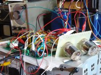
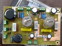
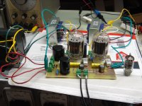
It could be made to work, but even with proper insulation there will be possible issues. We know that the SSE is tolerant of sloppy wiring. I expected a nasty humming, howling mess of noise and distortion when I made this clip lead furball with the tubes and OPT's offboarded, but it just worked at first power on. It was however driven by the test oscillator seen behind one of the OPT's and then a CD player. I guarantee that it would not have worked if driven by a turntable and phono stage. The furball of wires was eventually distilled down to create this SPUD board.
The wires from the plates of the output tubes to the OPT's carry about 900 volts peak to peak of signal voltage if the amp is played at full tilt. This will create a magnetic and electric field that can induce a low level voltage in other nearby wiring. Ordinarily this may cause a small unnoticeable loss of channel separation at high frequencies since all of the other wiring is carrying other high level signals. Wiring from the turntable to the phono stage and the phono stage itself will not like this kind of interference. This could create ringing, distortion, instability, and possible oscillation.
As Zung stated the best way to split up an SSE build is power supply on one chassis and board / OPT's on the other. That way the umbilical only carries low voltage heater power and high voltage DC with bypass caps on each end.
You could build the SSE board without the rectifier tube, and associated small parts, C1,C2,R1 and R2. The power transformer, choke, rectifier tube, C1 and C2 can all be mounted on the second chassis with the Aux cap if used. If an Aux cap is used C2 can be placed on the board, or in the power supply chassis. If C2 is in the power supply chassis, some kind of cap rated for 500 volts or more should be placed in the board for C2. If can be an electrolytic or a mylar cap of 0.1 uF or more just to keep signal voltage from the OPT's off the power supply wires in the umbilical.
Run multiple ground wires from one chassis to the other. If the ground goes open due to a broken wire full B+ voltage could appear between the two chassis leading to a deadly shock! Same with the offboard OPT setup. All conductive parts on each chassis MUST show continuity from one to another and to the ground pin on the power cord. Male plug goes on the amp chassis since it has exposed pins.
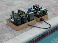
I built this 211 / 845 amp about 20 years ago using a separate power supply design. The amp uses an early prototype of the original TSE to drive a pair of 845 tubes which run on 1100 volts. There are two power supplies in the small chassis, one runs the TSE board, and the other runs the pair of 845's. The connectors are "Cinch Jones" connectors which used to be in available at Digikey. I still see some listed at Mouser. The published voltage rating is 250 volts. I used a connector with more pins than I needed, placed the 1100 volt pin at one end, and left all adjacent pins unused. The amp was used often for several years, but fell into disuse when I started building powerful sweep tube amps that ran on 500 volts or less. It was robbed for parts and the remains were sold at a hamfest a few years ago. The buyer just wanted the OPT's.
The wires from the plates of the output tubes to the OPT's carry about 900 volts peak to peak of signal voltage if the amp is played at full tilt. This will create a magnetic and electric field that can induce a low level voltage in other nearby wiring. Ordinarily this may cause a small unnoticeable loss of channel separation at high frequencies since all of the other wiring is carrying other high level signals. Wiring from the turntable to the phono stage and the phono stage itself will not like this kind of interference. This could create ringing, distortion, instability, and possible oscillation.
As Zung stated the best way to split up an SSE build is power supply on one chassis and board / OPT's on the other. That way the umbilical only carries low voltage heater power and high voltage DC with bypass caps on each end.
You could build the SSE board without the rectifier tube, and associated small parts, C1,C2,R1 and R2. The power transformer, choke, rectifier tube, C1 and C2 can all be mounted on the second chassis with the Aux cap if used. If an Aux cap is used C2 can be placed on the board, or in the power supply chassis. If C2 is in the power supply chassis, some kind of cap rated for 500 volts or more should be placed in the board for C2. If can be an electrolytic or a mylar cap of 0.1 uF or more just to keep signal voltage from the OPT's off the power supply wires in the umbilical.
Run multiple ground wires from one chassis to the other. If the ground goes open due to a broken wire full B+ voltage could appear between the two chassis leading to a deadly shock! Same with the offboard OPT setup. All conductive parts on each chassis MUST show continuity from one to another and to the ground pin on the power cord. Male plug goes on the amp chassis since it has exposed pins.
I built this 211 / 845 amp about 20 years ago using a separate power supply design. The amp uses an early prototype of the original TSE to drive a pair of 845 tubes which run on 1100 volts. There are two power supplies in the small chassis, one runs the TSE board, and the other runs the pair of 845's. The connectors are "Cinch Jones" connectors which used to be in available at Digikey. I still see some listed at Mouser. The published voltage rating is 250 volts. I used a connector with more pins than I needed, placed the 1100 volt pin at one end, and left all adjacent pins unused. The amp was used often for several years, but fell into disuse when I started building powerful sweep tube amps that ran on 500 volts or less. It was robbed for parts and the remains were sold at a hamfest a few years ago. The buyer just wanted the OPT's.
Attachments
If you're planning to use a wooden frame(s) with a metal top plate, you might consider one wooden frame with a visible divider the same thickness as your outer frame. This would let you put power supply on one side, OPT and circuit on other side and no need for an umbilical. 'twould make it larger & heavier however.
As others said, if space is the issue, as it seems to be, put the power supply in a separate enclosure and use an umbilical that can handle the load. I did that with a tube phono stage many years ago and it worked fine.
I have a plan to build an amp with the Toroidy potted transformers, and put them underneath, so they are 3 big feet. Then have a wooden case with aluminium bottom and top plates - possibly triangular - and the tubes on top.
It will be the Tubelab-erone 🙂
It will be the Tubelab-erone 🙂
Thank you all for your replies. Very enlightening information. I think ultimately the best option will be to continue playing around with my layout, and see if I can manage to cram it all into one plate. I was originally planning a wooden top plate, but for grounding purposes I will have to go with metal, so I'm going to be ordering a cut plate from Send-Cut-Send or a similar service. So I might as well make the plate as big as it needs to be, to fit the components properly into a single chassis.
We have a large-format 3D printer at work. I'm toying with the idea of using a 3D printed plinth with a metal top plate. That will eliminate the need for a laser cutter altogether. But it's possible I can still manage to cram everything into a plate that will fit in our 12x24 laser cutter, and go with the wood plinth I had originally imagined.
We have a large-format 3D printer at work. I'm toying with the idea of using a 3D printed plinth with a metal top plate. That will eliminate the need for a laser cutter altogether. But it's possible I can still manage to cram everything into a plate that will fit in our 12x24 laser cutter, and go with the wood plinth I had originally imagined.
I can strongly recommend splitting power and amp. I followed Andy Evans advice and it has the added benefit of making both boxes liftable.

I do love the look of the split chassis design, and I'm sure the external PSU has definite benefits. But at this point, my Tubelab SSE PCB is already populated, so I can't easily move the rectifier tube to another location.
On the sides, like The Princess Leia look?

How big did you plan your top plate to be? I have built a Tubelab SSE with a 10" x 12" top plate, but I used Toroidy toroids that were not potted.
How big did you plan your top plate to be? I have built a Tubelab SSE with a 10" x 12" top plate, but I used Toroidy toroids that were not potted.
The max dimensions of the laser cutter are 12x24. I was going to use the laser to cut pieces of plywood, then stack and glue to make a chassis plinth with a nice radius on it, so that means the top plate can be a max of about 11x23. I was going to make a trial plywood top plate, just to test the fitment, before sending the SVG off to a CNC place to have a sturdy metal top plate cut.
11 X 23 is quite large. One option is to rotate the board 90 degrees, have the rectifier and power transformer one side, then the output tubes and OPTs on the other side.
Do you have a drawing package? Can you show us where it is cramped?
Do you have a drawing package? Can you show us where it is cramped?
This is a layout I’m considering now. Part of me is thinking of ditching the massive toroidy OPTs in favor of something smaller.

Looks like plenty of space.
This is the format I think I will use next time. The rectifier to the back, OPTs on the side.

Where will you put the RCA inputs, speaker posts, on-off switch, indicator light, fuse and volume control? It is worth thinking how the input signal wiring will be routed.
My current one is built on an old cooker tray and is similar to your plan. I chopped the wrong side off the tray, so it is a bit congested underneath. The power transformer, choke and supplementary notor run capacitor are inside.
.jpg")
This is the format I think I will use next time. The rectifier to the back, OPTs on the side.
Where will you put the RCA inputs, speaker posts, on-off switch, indicator light, fuse and volume control? It is worth thinking how the input signal wiring will be routed.
My current one is built on an old cooker tray and is similar to your plan. I chopped the wrong side off the tray, so it is a bit congested underneath. The power transformer, choke and supplementary notor run capacitor are inside.
- Home
- Amplifiers
- Tubes / Valves
- External OPTs : Any reason why not?