joeling39 said:Another picture
Hi
From the picture I see that they did their utter best to place the crystal supporting capacitors as far away from the chip, well done boys, now the RF currents flow all over the board..........
Once you have measured and investigated these aspects, it is so easy........
regards,
Cutting Traces
Great idea Peter!
Maybe it is a SMT crystal, I have never seen a thingie exactly like this before.🙂
Peter Daniel said:What about just cutting traces, insted of removing?
Great idea Peter!
Maybe it is a SMT crystal, I have never seen a thingie exactly like this before.🙂
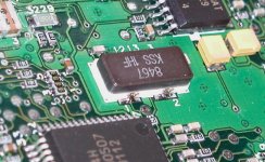
Peter Daniel said:Here's the better look, for everybody interested. It is SMD and shouldn't be a problem desoldering it at the 4 points.
careful guys, this SMD can be glued as well
Re: Crystal???
The glue is evil. But the Sony SCD1/777 one is real easy. Solder wick the joints, and use a 35W iron on the body. Came off straight away and still worked perfectly!!
-------------------------------------------------------------------Elso Kwak said:Hi Joe,
This looks more like a SMT crystal-oscillator to me, just as in the Sony SCD-1 or 777ES. Very difficult to remove!
Best done VERY carefully with a hot air gun.😎
Were some posts on AA on this issue.
The glue is evil. But the Sony SCD1/777 one is real easy. Solder wick the joints, and use a 35W iron on the body. Came off straight away and still worked perfectly!!
Re: Re: Re: Re: External clock to CD-PRO2
I measured other clocks as well (LC audio, my own and the HP reference clock), as well as the set up, which was clean to -80dB.
----------------------------------------------------------
Guido
I am going to toy with external word clocks separate from the source clock. Any experience of whta is a good one?
My system with your XO3 sounds significantly different on source clock and internal 10ppm VXCO clock with twin PLL and I don't know why? The setup cocnsist of the XO3 outputting into a dCS 972 DSD/24-192 upsampler. Inserting another twin PLL dejitter device in between changes the sound again and perhaps not for the better!
The influence of good 75R BNC and AES/EBU cables into proper terminations actually controls the character of the sound and is just as significant!! A Belden 1505A 4 m 75R cable sounds worst in the sense that the sound stage flattens and looses image precision.
Comments. anyone???
🙁
Re: Re: Re: Re: Re: External clock to CD-PRO2
Fred,
Wordclock: I have been thinking about this too, but cannot come any further than dividing, and eventually reclocking (I like D flipflops very much)
Do I understand correctly that your main clock is not a free running one close to the DAC?
Careful with cascading PLL's, as their poles should be well seperated.......
regards
fmak said:
Guido
I am going to toy with external word clocks separate from the source clock. Any experience of whta is a good one?
My system with your XO3 sounds significantly different on source clock and internal 10ppm VXCO clock with twin PLL and I don't know why? The setup cocnsist of the XO3 outputting into a dCS 972 DSD/24-192 upsampler. Inserting another twin PLL dejitter device in between changes the sound again and perhaps not for the better!
The influence of good 75R BNC and AES/EBU cables into proper terminations actually controls the character of the sound and is just as significant!! A Belden 1505A 4 m 75R cable sounds worst in the sense that the sound stage flattens and looses image precision.
Comments. anyone???
🙁
Fred,
Wordclock: I have been thinking about this too, but cannot come any further than dividing, and eventually reclocking (I like D flipflops very much)
Do I understand correctly that your main clock is not a free running one close to the DAC?
Careful with cascading PLL's, as their poles should be well seperated.......
regards
Re: Re: Re: Re: Re: Re: External clock to CD-PRO2
Wordclock: I have been thinking about this too, but cannot come any further than dividing, and eventually reclocking (I like D flipflops very much)
-----------------------------------------
Commercial ones are v expensive. I was wondering if there are good diy designs.
------------------------------------------
Do I understand correctly that your main clock is not a free running one close to the DAC?
-------------------------------------------
My dCS 972 ouputs double speed twin links to the 954 DAC. It has its own VCXO which can be enabled, or can lock onto the incoming clock. Alternatively it can use word clock or GPS reference.
The dac has its own VCXO with twin PLL.
So, I have XO3, twin PLL in 972, feeding twin PLL in 954. The latter two are designed to work with each other.
The arrangement is still very sensitive to choice of cable. A RG62 75R cable I bought from Farnell for £6 actually sounds rather good!
Sorry for my late reply - I was offline for a while 😎
Indeed the input clock pin is CRIN - 16.
Yes I modified more units type vae1250 which uses the same SAA7324. The simplest way is to desolder pins 15 and 16 from the pcb and feed clock into pin 16.
I will use CDPRO2 in my future cd-project and I'll be glad to share some results.
The overall sound was pretty good 😉 I recommend this modification.
A picture with cd-player that used this approach can be found
here
The product is no more available 🙁
Re: CD Pro clock
joeling39
Hi,
where did u bought the CDPRO2 from? locally or directly from daisy? and how much? i have lost ur email address..pls email me offline..thanks.
tone.
joeling39
Hi,
where did u bought the CDPRO2 from? locally or directly from daisy? and how much? i have lost ur email address..pls email me offline..thanks.
tone.
I am sorry Elso and Guido
The reason why the SAA7324 fail with your clocks is this:
Your clocks give out a 5 V signal but the SAA7324 is a 3.3 V chip. (Absolute maximum rating for input signals are: 3.6 V)... (See datasheet from above link).
This and other 3.3V chips will be destroyed with the KWAK clock even if correctly mounted........
And there is really no way of attenuating the clock signal without degrading the jitter performance on this type of standard CMOS oscillator.
Good luck guys .. ;o)
on this type of standard CMOS oscillator
i believe we have a conflict of interest........
"when correctly built and mounted - the kwakclock sounds better than the lcaudio xo2 clock"......

clock for SAA7324
Hi Lcaudio,
Don't be sorry, thanks for the hint.
May I suggest using the KWAK-CLOCK in this particular case with +/-3.3V supplies? This can simply be done by changing two resistors:
Make R5 8k66 and R8 12k. All other values remain the same. Best check the supply voltages before connecting the clock to this sensitive chip.
Except the one failure in this thread, possibly due to connecting a clock to pin 17 instead of pin 16, I have never heard of any failures.
😎
Correction
Yes Troels,
The KWAK-CLOCK is NOT a standard CMOS oscillator!

tbla said:
i believe we have a conflict of interest........
"when correctly built and mounted - the kwakclock sounds better than the lcaudio xo2 clock"......
Yes Troels,
The KWAK-CLOCK is NOT a standard CMOS oscillator!
?
It is a fact: there is no CMOS oscillator in my clock!!
😕 😕
999 posts, I can't believe it myself
Hi Lcaudio,LC Audio said:Not a very surprising statement coming from you 😉
It is a fact: there is no CMOS oscillator in my clock!!
😕 😕
999 posts, I can't believe it myself
Sorry i was a little fast on the trigger. You are right!
I confused your clock for another design sent to me a few days ago, and that one was just a simple CMOS can on a PCB. I will check it's name and post here later.
I searched the web for your design, and it seems to be OK.
I confused your clock for another design sent to me a few days ago, and that one was just a simple CMOS can on a PCB. I will check it's name and post here later.
I searched the web for your design, and it seems to be OK.


LC Audio said:I am sorry Elso and Guido
The reason why the SAA7324 fail with your clocks is this:
Your clocks give out a 5 V signal but the SAA7324 is a 3.3 V chip. (Absolute maximum rating for input signals are: 3.6 V)... (See datasheet from above link).
This and other 3.3V chips will be destroyed with the KWAK clock even if correctly mounted........
And there is really no way of attenuating the clock signal without degrading the jitter performance on this type of standard CMOS oscillator.
Good luck guys .. ;o)
Oh, I never got into this part of the discussion. Ofcourse a 3V3 circuit should be fed with a 3V3 clock......
Destroyed: I doubt, at least, when series resistance is used (what i do) as the clock input very likely has ESD protection diodes, able to handle 10mA, if my memory serves me right (I think that chip was still made in Philips C075 process)
Anyhow, we should respect the voltages
thanks
- Status
- Not open for further replies.
- Home
- Source & Line
- Digital Source
- External clock to CD-PRO2