Yay, this is my first post! After reading a ton of stuff in this forum, I have finally made myself a projector, still needs much work but at least I extended the flex cable...BY HAND!!! I went on a suggestion by some posts to extend it using thin wires, tape...and alot of luck. With a bit of sanding and many hours later I got a good method going. And yes I messed up a lot along the way! Extending this way is very tedious and requires a lot of time but it works... for me at least! I will post more on what I did and pics probably tomorrow evening after I finish cleaning a heap of mess, but here is a summary of what I did:
WARNING: Do not attempt this unless you are willing to risk a loss of a good lcd!!! It requires an actual cutting of the bothersome flex cable!
Things you will need: IDE cable (or very very thin wire since that is what will be extracted for the project), scissors, wide clear tape also thin tape if you want for small tapings, if you want to you can get 2 small permanent clamps to securely attach connections (don't even know if there is such thing since i didn't use any), and Lots of time and maybe touch up on your swearing skills cause you may get frustrated along the way.
Note: If you have a printer flex cable it is possible to cut the ends, trim it to specs with 20 thin wires (assuming that the wires are the same thickness and spacing as the ones on the flex of the lcd since printer flex cables have various wires on it, but it is very likely that you can find at least 20 wires meeting the specs) and sand it down to make an extension cable and attach that to the flex cable on the lcd and not have to go through most of this suff and even skip cutting the flex on the lcd too!
1.
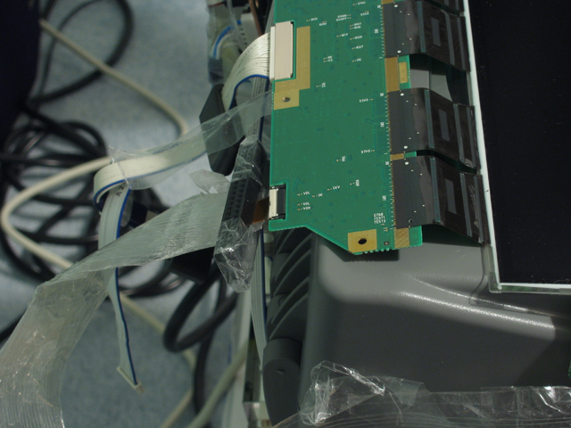
Cut the flex cable and sand both ends of the cut on the side where you see the copper wire as copper in color to expose the copper wires, do not sand the side that is black or dark.
2.
Use IDE cable and cut out it's wires at the longest part then rip out 3 separte wire bundles. Strip the entire bundle to use the thin wires that is inside (only need 20 there will be 7 wires per bundle x3 = 21 ). Use wide clear tape for the base of the home made extension cable and place 20 wires on it spaced evenly with at least 2 inches not on the tape on both ends (This part was very easy but it is also possible just to use 20 wire bundles attached and strip each end and trim to leave only one wire per bundle however you may find the wires may break off). Then overlap it with more tape to cover it keeping only the 2 inches on both ends exposed.
3.
Take the cut flex cable (the one not attached to the board) and place it half way over a piece of tape (or before the white marking on the flex calbe) with the sanded end over the tape and facing you. Lay it down on a flat surface and take your home made extension and place it on the other end of the tape making sure all the wires can overlap the flex cable to half the flex cable length and there is enough space between them for the next step, you may be trimming later also. (A picture will be posted probably tomorrow for clarity)
4.
Next use your fingers and a very small flat head driver and arrange the wires one by one on the tape to overlap one of the wire on the flex cable. As you can see the tape is there to hold the wires so they won't budge much once you set them in place on the tape with the flat head, takes a while. Don't worry about the end of the wires not positioned correctly (aka not flat on the flex cable since that end is not sticky with tape or it may be touching an ajdacet wire which doest really matter much at this point), just make sure each wire end is straight and the wire part that is on the tape is beside the edge of the wire on the flex cable you plan on joining.
5.
Once you set all the wires on, make sure the ends are straight and tape the ends of the wires on the flex cable leaving a space where the wires are supposed to connect to the exposed cables, don't worry of the wires are touching each other, the tape is there for more control for the next step.
6.
Since the wires are now held at both ends with an openging where the exposed flex cable is you can now easily arrange the wires with your very small flat head and separate each one from the other without it twisting back or doing some other wierd stuff.
7.
To easily check if the wires are on correctly take the flexcable cable and shine it with the black back facing a lamp and examine for only black bars (these are the copper wires on the flexcable) and no anomilies since any fine line you see means the thin wire is not straight on the cable and you have to arrange it again. After that is done tape the opening over and you may need to carefullly remove the other tape that was at the other end and trim the wires down unless it does not block the connection to the board.
8.
The tape does not give the wires good contact with the flex cable so you need to clamp the connection point on with something. I used the IDE cable's clamp (long plastic bar which i removed everthing leaving the 2 plastic pieces left then taped it all together) which worked well.
9.
Test each and every wire to see if the connections are good. I used a led light with 2 batteries for this and a thin stiff wire at the ends to touch the connetions one at a time, one test of a wire goes like this:
Touch one of the home made wire with the tester and touch the the other end of the tester on the fex cable wire that corresponds to it, if the led lights up then that wire connection is good, but also touch the wire on the flex cable beside the one you just tested to see if there is some cross connection problems.
10.
After that is done start on attaching the other end with the flex cable that should be also attached on the board. If you look carefully there are some connection points that are doubled ( on my samsung there is a circular imprint between the connections on the board that shows they are joined, so when testing you may see lights on the adjacent wires so don't be fooled.
Then that is it. Takes alot of time but if I can do it you can too...or maybe not, lol. As mentioned before I will post some pictures of what I did probably tommorow so don't worry if you are a little confused.
Post questions on this thread if you need some clarity.
Now all I need is some better lights for my cheap *** projector that doeasn't even dispaly the entire screen...Do flourex lights work good cause I had to resort to blowing the hot lcd with a stand fan. And this nearly 400 watt bulb that came with the OHP sucks, I can't even make out the people in mildly dim scenes.
WARNING: Do not attempt this unless you are willing to risk a loss of a good lcd!!! It requires an actual cutting of the bothersome flex cable!
Things you will need: IDE cable (or very very thin wire since that is what will be extracted for the project), scissors, wide clear tape also thin tape if you want for small tapings, if you want to you can get 2 small permanent clamps to securely attach connections (don't even know if there is such thing since i didn't use any), and Lots of time and maybe touch up on your swearing skills cause you may get frustrated along the way.
Note: If you have a printer flex cable it is possible to cut the ends, trim it to specs with 20 thin wires (assuming that the wires are the same thickness and spacing as the ones on the flex of the lcd since printer flex cables have various wires on it, but it is very likely that you can find at least 20 wires meeting the specs) and sand it down to make an extension cable and attach that to the flex cable on the lcd and not have to go through most of this suff and even skip cutting the flex on the lcd too!
1.
Cut the flex cable and sand both ends of the cut on the side where you see the copper wire as copper in color to expose the copper wires, do not sand the side that is black or dark.
2.
Use IDE cable and cut out it's wires at the longest part then rip out 3 separte wire bundles. Strip the entire bundle to use the thin wires that is inside (only need 20 there will be 7 wires per bundle x3 = 21 ). Use wide clear tape for the base of the home made extension cable and place 20 wires on it spaced evenly with at least 2 inches not on the tape on both ends (This part was very easy but it is also possible just to use 20 wire bundles attached and strip each end and trim to leave only one wire per bundle however you may find the wires may break off). Then overlap it with more tape to cover it keeping only the 2 inches on both ends exposed.
3.
Take the cut flex cable (the one not attached to the board) and place it half way over a piece of tape (or before the white marking on the flex calbe) with the sanded end over the tape and facing you. Lay it down on a flat surface and take your home made extension and place it on the other end of the tape making sure all the wires can overlap the flex cable to half the flex cable length and there is enough space between them for the next step, you may be trimming later also. (A picture will be posted probably tomorrow for clarity)
4.
Next use your fingers and a very small flat head driver and arrange the wires one by one on the tape to overlap one of the wire on the flex cable. As you can see the tape is there to hold the wires so they won't budge much once you set them in place on the tape with the flat head, takes a while. Don't worry about the end of the wires not positioned correctly (aka not flat on the flex cable since that end is not sticky with tape or it may be touching an ajdacet wire which doest really matter much at this point), just make sure each wire end is straight and the wire part that is on the tape is beside the edge of the wire on the flex cable you plan on joining.
5.
Once you set all the wires on, make sure the ends are straight and tape the ends of the wires on the flex cable leaving a space where the wires are supposed to connect to the exposed cables, don't worry of the wires are touching each other, the tape is there for more control for the next step.
6.
Since the wires are now held at both ends with an openging where the exposed flex cable is you can now easily arrange the wires with your very small flat head and separate each one from the other without it twisting back or doing some other wierd stuff.
7.
To easily check if the wires are on correctly take the flexcable cable and shine it with the black back facing a lamp and examine for only black bars (these are the copper wires on the flexcable) and no anomilies since any fine line you see means the thin wire is not straight on the cable and you have to arrange it again. After that is done tape the opening over and you may need to carefullly remove the other tape that was at the other end and trim the wires down unless it does not block the connection to the board.
8.
The tape does not give the wires good contact with the flex cable so you need to clamp the connection point on with something. I used the IDE cable's clamp (long plastic bar which i removed everthing leaving the 2 plastic pieces left then taped it all together) which worked well.
9.
Test each and every wire to see if the connections are good. I used a led light with 2 batteries for this and a thin stiff wire at the ends to touch the connetions one at a time, one test of a wire goes like this:
Touch one of the home made wire with the tester and touch the the other end of the tester on the fex cable wire that corresponds to it, if the led lights up then that wire connection is good, but also touch the wire on the flex cable beside the one you just tested to see if there is some cross connection problems.
10.
After that is done start on attaching the other end with the flex cable that should be also attached on the board. If you look carefully there are some connection points that are doubled ( on my samsung there is a circular imprint between the connections on the board that shows they are joined, so when testing you may see lights on the adjacent wires so don't be fooled.
Then that is it. Takes alot of time but if I can do it you can too...or maybe not, lol. As mentioned before I will post some pictures of what I did probably tommorow so don't worry if you are a little confused.
Post questions on this thread if you need some clarity.
Now all I need is some better lights for my cheap *** projector that doeasn't even dispaly the entire screen...Do flourex lights work good cause I had to resort to blowing the hot lcd with a stand fan. And this nearly 400 watt bulb that came with the OHP sucks, I can't even make out the people in mildly dim scenes.
excellent
Nice job. I extended the cable on one of my lcd's using conductive epoxy- a damn b!tch- but still holding on. I have another ex-monitor LCD and will take your method in regard this time.
Nice job. I extended the cable on one of my lcd's using conductive epoxy- a damn b!tch- but still holding on. I have another ex-monitor LCD and will take your method in regard this time.
Great post GTO.
Just a question. What about forgeting about the cable and soldering IDE wires to points on the board itself? I've hear that this works well.
Just a question. What about forgeting about the cable and soldering IDE wires to points on the board itself? I've hear that this works well.
Hell no!
It depends on the board and cable/ connector itself- in my case, there is absolutely no way to do it on the board itself- i have 26 within a 13mm across ribbon. This may be possible on models which have fewer or wider cables. This is just my experience though.
It depends on the board and cable/ connector itself- in my case, there is absolutely no way to do it on the board itself- i have 26 within a 13mm across ribbon. This may be possible on models which have fewer or wider cables. This is just my experience though.
Actually, I wasn't reffering to the connection points. Your right, that would be extremely difficult. I was thinking of alternative points that could be found w/ a voltometer or whatever. I'm sure those are spread out all over the board.
Here they are
OK some how the pics don't show so here is the link to the website I uploaded. CLICK HERE
I also resized the images to full res and added comments on the web page.
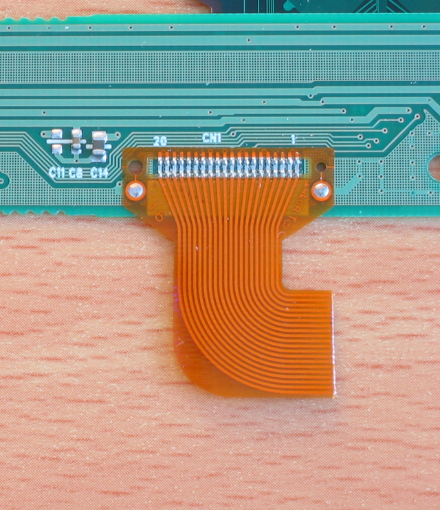
This image is of the cut flex cable. I used an x-acto knife instead of scissors for this job
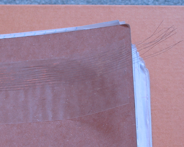
This image is of the home made extension, the wires are super thin.
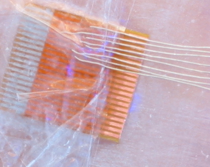
This image is one of my mistakes but its here just to show you how it is supposed to be placed on and pay attention to how much I sanded to reveal the copper. Don't do exactly what is on this image. I messed up while doing this cause as you can see I put tape on to make it straight each time I set one of the wire up so that left end got pretty thick and difficult to remove. I mage below has the correct method.
This is the image of the setting of the wire to the flex attached to the board. It's identical to what you wolud do for the other cut end.
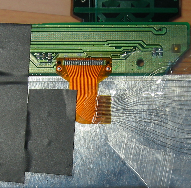
This one is of the completed end that is clamped with the Ide plastic with a bunch of tape, I used a game port add on card extender for the other one since it was smaller but basically the same thing just cut it if you want to make it smaller.
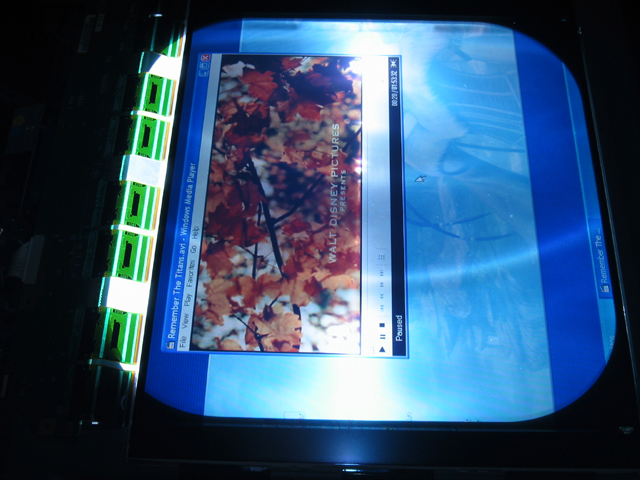
Finally the completed lcd turned on and fully functional.
GOOD LUCK for those trying.
OK some how the pics don't show so here is the link to the website I uploaded. CLICK HERE
I also resized the images to full res and added comments on the web page.
This image is of the cut flex cable. I used an x-acto knife instead of scissors for this job
This image is of the home made extension, the wires are super thin.
This image is one of my mistakes but its here just to show you how it is supposed to be placed on and pay attention to how much I sanded to reveal the copper. Don't do exactly what is on this image. I messed up while doing this cause as you can see I put tape on to make it straight each time I set one of the wire up so that left end got pretty thick and difficult to remove. I mage below has the correct method.
This is the image of the setting of the wire to the flex attached to the board. It's identical to what you wolud do for the other cut end.
This one is of the completed end that is clamped with the Ide plastic with a bunch of tape, I used a game port add on card extender for the other one since it was smaller but basically the same thing just cut it if you want to make it smaller.
Finally the completed lcd turned on and fully functional.
GOOD LUCK for those trying.
I would sugest thing .30 gauge wire from radio shack soldered directly on the pins!
Done that with a xbox mod chip ( 32 wires soldered on REALY TINY pad of ~0.5 mm )
Very solid and works well in my xbox for 6 month now!
Done that with a xbox mod chip ( 32 wires soldered on REALY TINY pad of ~0.5 mm )
Very solid and works well in my xbox for 6 month now!
Possible Brainstorm??
OK, I just had a possible Brainstorm while reading this thread. It don't know that much about electronics but.....wouldn't it be possible (maybe even easier) to use that paint that you get with the kits you use to repair the rear window defrost feature on your car? It carries electric current and is often used to overclock computer processors. With the paint and a little luck you could probably make a sort of "printed" ribbon extender...or am I totally wrong?? You can find examples of this technique by googling for "unlocking processor paint" and you'll find several articles about it.
OK, I just had a possible Brainstorm while reading this thread. It don't know that much about electronics but.....wouldn't it be possible (maybe even easier) to use that paint that you get with the kits you use to repair the rear window defrost feature on your car? It carries electric current and is often used to overclock computer processors. With the paint and a little luck you could probably make a sort of "printed" ribbon extender...or am I totally wrong?? You can find examples of this technique by googling for "unlocking processor paint" and you'll find several articles about it.
Wow, people actually view my post. Well your idea is a possibiility so long as you can match the width of each connection point and the spray is of good conductive substance, you could spray yourself a good homemade ribbon on some flexable base such as tape. Then simply join it using clamp mechanism or if you are really good use some of that conductive adhesive on it.
I just read the last few posts so dont shoot me.....get a thin strip of mylar and use copper tape
Possible Method...
I'm thinking of a method where you could stick a piece of wide electrical tape on a piece of bristol board and flip it over. Then you would carefully measure out the width and number of connections, carve them out of the bristol board with a razor or exacto knife and then paint in the channels. After that, peel off the electrical tape when it is dry and stick it to your real ribbon cable with the traces lined up and just cover your painted traces and sticky side of electrical tape with another piece of tape. I really want to give thing a try to see how practicle it is but I don't have any ribbons to practise on. Anyone know of a good source of practise ribbon???
I'm thinking of a method where you could stick a piece of wide electrical tape on a piece of bristol board and flip it over. Then you would carefully measure out the width and number of connections, carve them out of the bristol board with a razor or exacto knife and then paint in the channels. After that, peel off the electrical tape when it is dry and stick it to your real ribbon cable with the traces lined up and just cover your painted traces and sticky side of electrical tape with another piece of tape. I really want to give thing a try to see how practicle it is but I don't have any ribbons to practise on. Anyone know of a good source of practise ribbon???
That method would be quite difficult since the space to carve the channels are quite narrow (my flex cable has 20 connections spanning 13 mm that's less than half a millimeter per connection) and bristol board is just thick paper and will not give you a repeatable perfect clean carve or cut each time.
My suggestion would be to make a pattern on the computer using a cad sofware or photoshop such that the design at one end will match the with and spacing of the original flex and the other end will widen out to easily connect with some cable. You will have 2 of these patterns printed, one for each end and appropriately cut (read next paragraph for my thoughts on this), and lay them on top of a peice of tape carefully and it will stick on permanently. Then spray on conductive adhesive and once it's ready, scrape the paper away or if you have made a lip of some sort that you can hold on to pull out at least the top layer.
I suggest the patterns to be cut using a x-acto knife and is preferred that you cut inside the paper the openings such that the extra paper between the slits are still held on to the surrounding paper . IE: don't make the pattern to be cut by scissors on the edge of the paper, print the pattern in the middle and make a cutout just like if you are doing a regular spraypainting with a cutout mask where no sections are left dangling and possibly curl making it difficult to paste on to the tape.
WARNING:
This is only a suggestion and has not been tested. Use this information at your own risk.😉
took me a while to picture what you were saying But Now I get it, So basically your just making a stencil, also where is this " conductive" spray paint located at? I have never heard of such a thing. Thanks Oh sorry for Just busting on this conversation.
there is a product out there that repairs circuit traces...its a 0.1 mm marker tip that would definately be fine enough....I have used it with good results....................so my other idea is as follows.....make a template of the ribbon cable and print it out on a peice of 3M clear acetate and basically fill in the traces
Cheers!!The DIRT®
Cheers!!The DIRT®
I should have done that bitbyter. 🙂 Yes this method does work... although he doesnt explain it very well.
I also found IDE cable to be very hard to work with. 30 gauge insulated wire was much easier to handle.
I also found IDE cable to be very hard to work with. 30 gauge insulated wire was much easier to handle.
howdy all i was just talking to mikinner last week about this idea, its the same as gtoturbo's but a little diff in the end product, ide cable was the go but the ultra ide not the regular stuff i asume u guys are using this lol as its smaller, same thing i told mike cut the cable and sand it bla bla lol but i was thinking in soldering it, it can be done if u tin the wire first with solder trim it to length and put a tiny bit of soldering flux on the cable, that way all u have to do is just touch it ever so fast and lightly with the iron for it to solder and stick, test it then super glue the wires ect, then after that i was thinking in getting an ice creame stick cutting it to size to glue to the cable as like a back bone then a small amount of heat shrink over that to keep it all tight and strong. Anyway thats my idea on the matter lol id be careful with that electrical cunductive glue cos u wouldnt want to short it out lol
Trev
Trev
- Status
- Not open for further replies.
- Home
- General Interest
- Everything Else
- The Moving Image
- DIY Projectors
- Extending the cable. I've done it!