Disconnecting the gates of mosFETs can leave the charge on the gate at some random value.
The FET could be fully on or Fully OFF or some intermediate level of conduction.
The relay should take the gate to some fixed level to ensure the conduction state is what you require.
It's a DPDT relay - when they're switched off the gates are connected together and pulled to ground via 1K. The thing that I'm not entirely sure of is what happens when there's a small time difference between one FET and the other switching into circuit. I presume that as long as the offset voltage is nulled out the voltage at the output of the VAS will be very close to 0V. When one gate gets switched to the VAS it'll charge to equalise, then when the other hooks up it'll even out. There'll be a thump, due to the FETs going from 0 bias to 100mA, but the question is how big will it be. I'm hoping quite small.
Anyway I've used some itty-bitty Omron G6K signal relays to switch the gates. My hope is that by switching both sides of a given output stage with the one DPDT relay they'll be coincident within a millisecond or so, minimising disruptions.
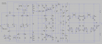
Here's some more development. I've gone away from the IMT4 and IMX8 duals on the basis that they're a little fragile, both physically and in terms of dissipation. More cascoding in the VAS, plus addition of a passive DC servo.
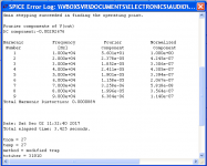
4 pairs of MOSFETs gives me a reasonable output power of 200W into 8 Ohms with +/-65V supplies.
Simulates <1ppm at 10KHz.
4 pairs of MOSFETs gives me a reasonable output power of 200W into 8 Ohms with +/-65V supplies.
Simulates <1ppm at 10KHz.
Attachments
Last edited:

...Simulates <1ppm at 10KHz.
That is a remarkable number, if the simulation is accurate.
What model have you used for the FETs?
Best wishes
David
That is a remarkable number, if the simulation is accurate.
What model have you used for the FETs?
Best wishes
David
Cordell's.
* 2SK1056C VDMOS copyright Cordell Audio December 6, 2010
.model 2SK1058 VDMOS(nchan Vto=0.02 Kp=0.85 Lambda=0.02 Rs=0.62 Rd=0.1 Rds=1e7 Cgdmax=100p Cgdmin=5p a=0.25 Cgs=600p Cjo=1080p m=0.7 VJ=2.5 IS=4.0E-06 N=2.4 mfg=Renesas)
* 2SJ162C VDMOS copyright Cordell Audio December 6, 2010
.model 2SJ162 VDMOS(pchan Vto=-0.08 Kp=0.6 Lambda=0.1 Rs=0.55 Rd=0.1 Rds=1e7 Cgdmax=215p Cgdmin=10p a=0.25 Cgs=900p Cjo=1200p m=0.7 VJ=2.5 IS=4.0E-06 N=2.4 mfg=Renesas)
Cordell's.
Ok, thanks, that removes most of my main concern.
Bob did some later work to use the updated sub-threshold conduction parameter in VDMOS models.
There may be more up-to-date models, possibly on DIY rather than Bob's website.
That's just FYI if you want the best, but they probably won't alter the distortion dramatically.
What does the Return Ratio aka Loop Gain look like?
Best wishes
David
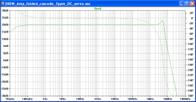
I've got a bit of a peak (perhaps 3dB) at ~5MHz. I've attached open and closed loop plots.
Note for open loop I increased R10, R64 & R66 to 9Meg, 470Meg and 100Meg respectively. I've got ~70deg phase margin with gain set to 20dB.
Note for open loop I increased R10, R64 & R66 to 9Meg, 470Meg and 100Meg respectively. I've got ~70deg phase margin with gain set to 20dB.
Attachments
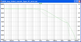
Hi Suzy, so for gauging stability the approach is first nullify with a 0v transient response, then set all NFB resistors very high so that when AC simulation is run you get the open loop gain plot, from this read off the phase shift at your standard closed loop gain 20dB in this case. The difference between this and -180 is the phase margin.
Seems I've been misreading my textbooks because I thought you had to have a clear phase margin at 0dB from the closed loop gain AC response. Which means I've been over compensating my builds! On the plus side revisiting my builds will get some THD back I guess.
What's the recommended ballpark for phase margin, 70 degrees sounds pretty healthy?
Cheers & thanks again
Nick
...Note for open loop I increased R10, R64 & R66....
Once you alter the resistor values then the internal loads on the circuit vary and the subtraction of closed loop from open loop is not accurate because they are two different conditions.
Hopefully the effect is minor but why not use a Tian probe and eliminate it completely?
It is more critical in your circuit because you have some embedded positive feedback.
Best wishes
David
Hi Nick, A better technique is the Tian probe, included in the LTSpice examples.
Last edited:
I have no excuse, save that I’ve been doing it the same way for many years and have no complaints. The difference in operating condition for the input stage is minor, as the impedance it sees is dominated by R48. The whole Tian probe thing confuses the hell out of me.
What's the recommended ballpark for phase margin
It depends. If I can really trust models and don’t mind some peaking I’d be happy enough with 60 degrees.
There’s nothing wrong for compensating for unity gain. At least it’s not going to oscillate 🙂
Ha ha thanks Suzy you're right - and explains why on my scope I never see any oscillation even when dipping the Miller compensation below calculated values, have built with the calculated value though being a bit of a chicken.
What do you both think about Bob Cordell's method of inserting a very large inductor on the NFB path for open loop measurement? This keeps the DC characteristics and blocks AC feedback, pretty simple to do because there's no need to change other circuit values.
What do you both think about Bob Cordell's method of inserting a very large inductor on the NFB path for open loop measurement? This keeps the DC characteristics and blocks AC feedback, pretty simple to do because there's no need to change other circuit values.
Actually his method is a bit more complicated than that for measuring OLG because you also need to relocate the signal source to the -ve input via a resistance equal to the larger NFB resistor which itself is replaced by a 1000G inductor and also ground the +ve input.
Just found out you can still buy TO-71 packaged U401 dual JFETs (from futurelec). All the transistor changes I made are TO-92 or TO-126, so there’s nothing in principle preventing this from being laid out completely through-hole.
...the same way for many years and have no complaints...
The enormous resistor (or inductor) works OK for typical amplifiers.
I would be hesitant to rely on it for an amplifier with a substantial peak in the MHz.
Even more so since the peak occurs even before any simulation of stray inductance in the supplies, capacitive loads, and other real world effects.
While the Tian theory is not that obvious, the actual use is quite simple - just copy the probe and run it, plot the expression that Frank Wiedmann worked out (he probably deserves at least shared name credit)
One other point I just noticed, your second section of current mirror loaded LTPs looks a little like the Randy Slone amp that was notorious for it's poor bias stability, despite the fact it simulated superficially ok.
Have you considered this or checked it with simulations of inevitable real world mismatched components and temperatures?
If you have considered it then how is the bias keep stable? I don't see it off-hand.
Best wishes
David
The second stage is biased with a conventional LTP, so that’s reasonable. The VAS stage is the potentially problematic one, as it takes it’s bias from the clamped mirror loads of the second stage. I’ve simulated with deliberate mismatch in the current mirror transistors, and the VAS current stays reasonable.
The diode clamp around the current mirrors are the key to keeping the bias stable. I also add another pair of diodes between VAS supply and the supply for the preceding stages that gives me two diode drops rather than just one for better defining VAS current.
The diode clamp around the current mirrors are the key to keeping the bias stable. I also add another pair of diodes between VAS supply and the supply for the preceding stages that gives me two diode drops rather than just one for better defining VAS current.
OMG, I completely forgot about this amp.
I needed something quickly for my noisePlank speakers, so I jammed a couple of my little 50W amps into a hammond enclosure, running at +/-24V, at reduced bias.
Then I got all enthused about diamonds. This one is languishing, mainly because I designed it in Protel, and now work almost exclusively in KiCAD on my mac.
You could also use CircuitMaker, a free Altium software but the drawback is that everything is public and open source... and use Parallel Desktops on your mac. Maybe KiCAD is a better alternative after all.
Free PCB Design Software | CircuitMaker
Free PCB Design Software | CircuitMaker
I tried circuitmaker years ago, in the hope that I could free some of my many Protel designs, but it like Protel is proprietary. And having run everything on a Mac for a long time I hate having to fire up virtual windows machines on the mac.
So I forced myself to learn KiCAD, and haven't looked back. I can still access my Protel stuff if I really need to with an old copy of Protel 98 and an equally old PC running XP (or in a virtualbox XP install on the mac), but I'm doing everything in KiCAD now.
KiCAD is really wonderful. It's properly open, runs on anything, is super stable, has no arbitrary limitations, isn't ridiculously bloated and makes really gorgeous schematics and PCBs...
Last edited:
- Home
- Amplifiers
- Solid State
- Extending the AEM6000 design to ppm THD