Around 30.000uF total.... 20.000 at the supply
And 10000uF near the amplifier..bypassed by 100N.
15.000uf each rail....i had more but i decided to reduce them.
regards,
Carlos
And 10000uF near the amplifier..bypassed by 100N.
15.000uf each rail....i had more but i decided to reduce them.
regards,
Carlos
Hi Mike,
Well, I checked them when I got home tonight and no luck. They are both still drawing too much current.
I'm etching a couple more boards as I type this. I will assemple them without tinning the traces this time and see how it goes.
I don't suppose you have a silk screen of the componants that doesn't have a black background do you? I think part of my problem may have been trying to work off of that Eagle top view. The componant numbers and values are very difficult to see when printed.
Thanks, Terry
latest sym5
hi mikeB,
I have etched the pcb of latest sym5 and would use c5200/a1943(fairchild), 10pf for feedback network and .15E as emitter resistance.
am i missing anything......!!! or are these mods ok ???
plz.....help.....
🙂 🙂
aman
hi mikeB,
I have etched the pcb of latest sym5 and would use c5200/a1943(fairchild), 10pf for feedback network and .15E as emitter resistance.
am i missing anything......!!! or are these mods ok ???
plz.....help.....
🙂 🙂
aman
Hi aman, i don't see any problem. I don't know the fairchild devices, but fairchild devices are typically quite good.
Mike
Mike
low input from dvd
hi MikeB,
I m getting low input signals from my dvd which not seems to be enough for the sym5(tested from the two sym5,(the previous layout) which i built earlier ).
could i increase the value of feedback resistor to encrease the gain... to get the required output...??
could it be done without any unwanted problem..?
aman
Hi aman, you shouldn't play around with the feedback network, that's delicate. I am confused, signal from DVD is similar to CD, the gain of symasym is high enough to be driven into clipping by such signal ? 0.7v does drive it into clipping. CD has typically nearly double that.
What is the size of the volumepot you are using ? I recommend to not use bigger than 22k here. A preamp might be better choice here.
You're the first one saying that symasym has not enough gain... 😀
Mike
What is the size of the volumepot you are using ? I recommend to not use bigger than 22k here. A preamp might be better choice here.
You're the first one saying that symasym has not enough gain... 😀
Mike
sym gain
hi mikeB
ohhh.... no... who am i to say anything abt this great amp..🙂
It played amazing when i fed with a signal of abt .8volt .
I was only thinking whether i could go without the preamp..
thanks for ur great suggestion.
In fact i was afraid of touching the circuit of the sym5 so i just asked ur permission....😀
regrds
Aman
MikeB,
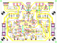
The latest layout seems ok in regard of separate ground traces for input ground and decoupling ground. But don't you think it would be better to join the decoupling ground coming from left and right side not in the single point in VGND.
For me it looks that assuming there are higher currents flowing with higher power output the VGND point will be modulated a little and this right away influences the input ground also.
I would do it something like this....
Regards,
Ergo
Attachments
Hi Ergo, thanks for the suggestions, but this was already an "old" layout, you can see new one here:
http://www.diyaudio.com/forums/showthread.php?postid=783283#post783283
It has different grounding scheme.
Mike
http://www.diyaudio.com/forums/showthread.php?postid=783283#post783283
It has different grounding scheme.
Mike
Ergo!
Here it is:
Here it is:
MikeB said:Hi !
I've uploaded latest files for PCB:
Quasi Silk screen 80kb
File for print out (600dpi,zipped bitmap) 45kb
Eagle files 37kb
Don't forget, it's not fully tested, i just made one board and it worked fine...
The REs in input-LTP are reserved and can be skipped by 2 small wires. (just wanted to have the possibility,principally with 22ohms they enable to increase the 499ohm in feedback to 1k to lower gain, not tested yet)
matteson, i have no experience in getting pcbs produced, i always etched them. But your proposal sounds completely correct and should work.
Mike
Hi Mike,
Have you had any more time to test the newest design. It just dawned on me that I should probably etch the new one instead of populating the older one. I've already etched the older one but Thought I'd go ahead and etch the newer ones too.
What do you think?
Thanks, Terry
Have you had any more time to test the newest design. It just dawned on me that I should probably etch the new one instead of populating the older one. I've already etched the older one but Thought I'd go ahead and etch the newer ones too.
What do you think?
Thanks, Terry
Stillforgiven, you are a great nice guy, and i think you deserve the happiness to
Listen to a very good audio amplifier.
I am always observing and following nice guys threads, this is the way i have to compensate those that are deceptive...but they are not more than 20 percent...it is normal.
I am happy that you are together with Symassym.
Congratulations, a good decision you made.
regards,
Carlos
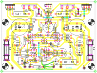
Hi Terry, i've already approved the new pcb: http://www.diyaudio.com/forums/showthread.php?postid=792540#post792540
I did more listening, it does sound great. It's not tested like the old one yet, but i do not see problems.
I will update my page the next days, but likely after x-mas.
But, if you've already etched the boards... The older board is a bit easier to solder, the new one has more wire jumpers.
-----------
About the 22ohms in the supplyrails to the frontend, as Carlos pointed out, these are too small. I've spent some hours in sims, 47ohms showed the best behaviour, "matched" poles... I tried out increasing them and listened, with the 47ohms the quality slightly improved, a bit more dynamics and bass punch. I recommend 47ohms here... Thanks Carlos !
Possibly the drop in PSRR for low frequencies can be further moved to lower freqs by increasing this resistor even more, but not eliminated. I attached psrr graph, green = original 22ohms, red = 47ohms,blue = 100ohms.
It can be eliminated by cascoding the input devices, but this will be a new revision again. Maybe i will try...
I am completely happy with the quality now, so i am not sure if i will really try further modifications.
I observed that having a high impedance signal source also has a negative impact on low freq psrr. Using high gain high quality devices like the mpsa18 does help with this "issue".
Mike
Attachments

12 Cents said:What is high impedance in the source?
Conventional CD output, potentiometer before input etc. Read my "review" and note mentioning active preamp. Buffering is very good, too. These things must be tried and compared together, otherwise people do not belive ... 😉
High impedance would be ~ >1kohm, good preamps have zout below 100ohms and should not show problems. Having a volumepot directly connected to the symasym could decrease quality. I don't know how big the effect is, i have a volumepot (22k) and can't complain...
This is only about getting the last drops of quality out of symasym... 😀
There is no problem... Nearly all poweramps are sensitive to that, this just explains why. (or one of the reasons)
Mike
This is only about getting the last drops of quality out of symasym... 😀
There is no problem... Nearly all poweramps are sensitive to that, this just explains why. (or one of the reasons)
Mike
The effect is extraordinary. Not only low Zout, but also high current capability of the previous stage is of a great help.
I really do not intend to go to any theoretical discussion on this matter, this is jus an experience told to public, verified on tens of amplifiers and CD players with the same results.
I really do not intend to go to any theoretical discussion on this matter, this is jus an experience told to public, verified on tens of amplifiers and CD players with the same results.
- Home
- Amplifiers
- Solid State
- Explendid amplifier designed by Michael Bittner, our MikeB