Pink,
your All Crooked teeth avatar is very becoming.
I can help you out with K170s when you start thinking Sym Modding.
your All Crooked teeth avatar is very becoming.
I can help you out with K170s when you start thinking Sym Modding.
Thanks Jacco.
I am trying to get some of my backlog of half finished projects completed at the moment, once I've done that, I may well take you up on your offer.
I am trying to get some of my backlog of half finished projects completed at the moment, once I've done that, I may well take you up on your offer.
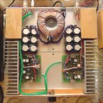
Re: Beautifull construction...one of 10 ultimate constructions made in this forum
Very nice, but I don't see a fuse or mains switch. Naughty! 🙂
destroyer X said:Sheldon have constructed also a pretty one...
Very nice, but I don't see a fuse or mains switch. Naughty! 🙂
Re: Beautifull construction...one of 10 ultimate constructions made in this forum
Yes, very nice, this one is from Borys i think.
Al, isn't that more a pinkbear than a pinkmouse in your avatar ?
Mike
destroyer X said:
Sheldon have constructed also a pretty one...this one is Pinkmouse construction if think.
Really pretty.
regards,
Carlos
Yes, very nice, this one is from Borys i think.
Al, isn't that more a pinkbear than a pinkmouse in your avatar ?
Mike
Al, isn't that more a pinkbear than a pinkmouse in your avatar
Hmm, an attempt to undermine a moderator's authority. If I say it's a mouse, it's a mouse, and that's final!
🙂
MikeB said:Ooops, hmm, so the sky is indeed pink ?
I say yes, but ABX testing would seem to indicate not, so the test must be flawed on a fundamental level.
Mike,
i can vouch for Al.
I live in a big old house, infested with mice.
Returning from evenings of dance and drinks i've killed many a number that looked completely identical to Al's avatar.
i can vouch for Al.
I live in a big old house, infested with mice.
Returning from evenings of dance and drinks i've killed many a number that looked completely identical to Al's avatar.
jacco vermeulen said:Mike,
i can vouch for Al.
I live in a big old house, infested with mice.
Returning from evenings of dance and drinks i've killed many a number that looked completely identical to Al's avatar.
Hmm, i guess they looked like that because of a broken neck ?
If not, i'd immediately move out...
Mike
Hey guys!
I don't have much of a way of making circuit boards... Anyone have a point-to-point soldering diagram? 😀
On the serious side, exactly how sane is it to try to wire SymAsym this way, and what do you think that the outcomes would be? If I'm crazy enough, I might even attempt it!
keantoken
🙂
I don't have much of a way of making circuit boards... Anyone have a point-to-point soldering diagram? 😀
On the serious side, exactly how sane is it to try to wire SymAsym this way, and what do you think that the outcomes would be? If I'm crazy enough, I might even attempt it!
keantoken
🙂
Hi keantoken,
Use a 10 div / inch breadboard. Make sure your wiring exactly follows the pattern and use heavy conductors for the supply and ground traces. It should be okay if you are careful but more work on your part.
-Chris
Use a 10 div / inch breadboard. Make sure your wiring exactly follows the pattern and use heavy conductors for the supply and ground traces. It should be okay if you are careful but more work on your part.
-Chris
10 divets per inch? I am afraid I don't have a breadboard large enough to contain symasym, but Radio Shack has a big one I can buy. I am sorry to keep everybody waiting. I just have more than one thing going on in my mind now because of school and my grandma writing a book about her experiences with polio (called The Bittersweet Pain of Polio, except that is the decided name for now.), my mother trying to write a book about being the daughter of a polio survivor with polio herself (called Surviving a Polio Survivor, it is a very early naming idea, though.). So please be patient with me.
Will anyone give me their SymAsym file that they are simulating successfully with LTSpice so that I may be able to find out what is wrong? Or Does no one simulate SymAsym with LTSpice?
Will anyone give me their SymAsym file that they are simulating successfully with LTSpice so that I may be able to find out what is wrong? Or Does no one simulate SymAsym with LTSpice?
keantoken said:Hey guys!
I don't have much of a way of making circuit boards... Anyone have a point-to-point soldering diagram? 😀
On the serious side, exactly how sane is it to try to wire SymAsym this way, and what do you think that the outcomes would be? If I'm crazy enough, I might even attempt it!
keantoken
🙂
I made my first two that way. They work fine, after sorting out some problems with bad transistors (it was either that, or a bad connection). I just took the schematic and built from the input out, following the way the schematic is layed out. But to do it again, I would do as Chris suggests. Get perf. board, print out the board layout to scale and just follow that. It will be much easier. There's no reason it shouldn't work just as well as the printed board. The crew here can tell you how to print. Make sure you get a copy of the top of the board, so you know where to place jumpers (not essential, as you can figure that out from the schematic, but it will be easier having the top side view).
Or, you can buy a board making kit like this: http://www.radioshack.com/product/i...cuit+board&kw=circuit+board&parentPage=search
Carlos is an expert at doing it this way. I know that he's described his method in some detail here somewhere. My next prototype will probably be done this way.
Sheldon
What do you use for heatsinking the components? Do you just use one of those heatsink clamps that come with most Radio Rhack soldering kits?
Who knows... Maybe one day I'll design some point-to-point soldering diagram software. 🙂
Who knows... Maybe one day I'll design some point-to-point soldering diagram software. 🙂
keantoken said:What do you use for heatsinking the components? Do you just use one of those heatsink clamps that come with most Radio Rhack soldering kits?
Who knows... Maybe one day I'll design some point-to-point soldering diagram software. 🙂
I use aluminum plate and thermal grease between back and sides, so that the three surfaces act as a heatsink/radiator. See here for example - also on perf board: http://www.diyaudio.com/forums/showthread.php?postid=737581#post737581
Sheldon
edit: And here with printed boards - this one stereo, same type of heat management: http://www.diyaudio.com/forums/showthread.php?postid=862086#post862086
I have an older Pioneer amplifier that has functioning 2SA1302 and 2SC3281's in it. I have no interest in the rest of the amp, but would like to build this one over the Winter...hopefully with parts form the Pioneer. Is there a BOM that someone has for this amplifier?
This will probably end up being an amp for multi-amping in the future.
EDIT: So...looked at the site...got my answer for the BOM. What issues do I face with using the Toshibas I have?
This will probably end up being an amp for multi-amping in the future.
EDIT: So...looked at the site...got my answer for the BOM. What issues do I face with using the Toshibas I have?
Hi Aaron,
Compensation issues. Try to build compensating as the other Toshiba parts. Your outputs are a little smaller too, so watch low impedance loads.
-Chris
Compensation issues. Try to build compensating as the other Toshiba parts. Your outputs are a little smaller too, so watch low impedance loads.
-Chris
- Home
- Amplifiers
- Solid State
- Explendid amplifier designed by Michael Bittner, our MikeB