Like I said, I'm left handed. - one of the few in their right mind!
Me too !
I had both a huge 200W genesis class A and my present 200W class AB.
NO real difference in sound , no difference in the scope with high output.
Just a lot more heat on the class A.
I can underbias the AB to see a slight "glitch". The control of the speaker
is more the damping factor of the output stage and the speaker itself.
A or AB - does not matter.
THD wise , a large class A stage will free the NFB of a ppm input stage
from trying to correct that little non-linearity at the crossover. A
simulated A output stage would be 1-2ppm versus 20-30ppm for the
AB stage. Nothing to really justify all that heat.
OS
You guys have good points, but I can hear my amp leaving Class A in my planar speakers (Renaissance 90s) 4 ohm
Voltage controls the current, it follows the voltage. Wattage = work = Volts * amps
so they both do the work, but voltage leads except through a capacitor in series.
In the case with the capacitor, current must flow to raise the voltage across the pins - but in reality the voltage is pushing the whole circuit, it is explained this way so the process is understood in the brain, concerning the capacitor terminals and the charge.
Voltage is required to move electrons.
Voltage control, with the current to back it up
equals success.
You have to have class A in front of it entirely, and op amps don't help.
A lot of people haven't really heard a good quality, full Class A system,
they do not notice the haze, because they have not heard a lack of it.
My amp runs 18 watts of Class A. My pre is full Class A. My old pre was not.
It made a very noticeable difference when I changed it. The clean sound would
stay cleaner to a higher volume, and I can tell now when the big amp is leaving Class A, because the pre does not anymore.
I'm talking about quality, clean sound. Not just clear, but pristine clean sounding.
a little distortion here sticks right out and is obvious.
If someone would have explained it to me like I said it on the first post, I would have understood what class A really was years ago.. I knew about being biased half way up, but it was not said why in a way I could understand.
Controlling the voltage on the downswing to fall faster than natural - if required!
I've heard a lot of amps too, AB amps differ, some are harder to tell.
Like B&K amps, run about 40mv of bias, hard to tell - but, the parts are kinda
crammed on the little cards, giving similar sound to AB anyway!! (B&K 200.2)
A Parasound HCA1500 had 70mv of bias, sounded cleaner and more detailed - parts are more spread out - but could tell when leaving class A. a little haze or shrillness in the upper/inner details of the upper midrange.
You're trying to explain the difference in sounding only by the difference in output stage operating principles. It would be good if it would be that simple. Unfortunately, it's not.
A modern, properly designed class AB amplifier will not show any disadvantages because of the fact it's output stage is not class A. It will sound crystal clear, no compromise.
A proper blind test is showing the same.
Class A does not involve any switching by design, but then it's all about linearity. Can you make it linear enough?
Another interesting point - class AB with no switching. None of the output devices ever switch off. Allows extremely low distortion, preserving the energy efficiency.
Voltage amplification stages, starting right from the input - topology, transients handling, slew rate, inter-modulation and ... linearity again - lots of things influence the sound, being independent from the output stage's class of operation.
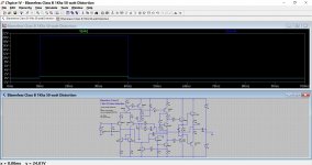
Class A operation retains control of the voltage as it falls towards zero, even from the peaks of either side.
- there are times that the voltage needs to drop faster than it would naturally fall............... Keep in mind that the opposite polarity transistor cannot pull the voltage towards zero until it's bias is reached, which is usually not far from zero volts.
This shows a typical Class AB amp (described by its designer as a blameless Class B) that is biased to around 100ma.
The load is a 100uf capacitor of 0.08 E.S.R. Totally unrealistic, however...
Question :
If we apply a step function of 1 volt peak to the input, why does the output voltage NOT remain at the nominal level of 21 volts.
In other words, if (as you say) the lower transistor has no control in being able to 'pull' the voltage down... then what does ? Why does the cap not remain charged ?
Attachments
ou guys have good points, but I can hear my amp leaving Class A in my planar speakers (Renaissance 90s) 4 ohm
Voltage controls the current, it follows the voltage. Wattage = work = Volts * amps
Then you have the cacti or mushroom within you.
To hear 3-30ppm is quite subjective , I suppose you might need that psilocybin to discern "leaving class A" while listening.
I actually use these things , and can actually see these minor artifacts float
across the room . Monkeys will be monkeys.
(not to denigrate the present state of human DNA).
OS
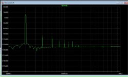
There you have a 100W artifact , your speaker would be beaming 100X
that distortion right in your face. The amp would be quite the background
"performer". Speaker is at 1% distortion , BTW.
PS- this is what I give the forum , but can not make their speakers "blameless".
booo hooo !!
OS
that distortion right in your face. The amp would be quite the background
"performer". Speaker is at 1% distortion , BTW.
PS- this is what I give the forum , but can not make their speakers "blameless".
booo hooo !!
OS
Attachments
Scopes don't lie. If the output has (next to) no distortion on the scope, you won't hear distortion. I was all for class A, until I achieved the same quality but much more power with my class AB designs. Class AB - there is always a little class A in there, and rightly so.
Scopes don't lie. If the output has (next to) no distortion on the scope, you won't hear distortion. I was all for class A, until I achieved the same quality but much more power with my class AB designs. Class AB - there is always a little class A in there, and rightly so.
Well, this is also not that easy 😉
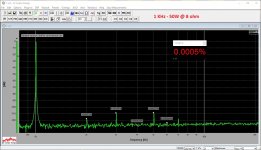
Oscilloscope is not that precise, you will not see some 2-nd + 3rd harmonics at the level of 1% THD on the scope sine curve, however you will hear it. But you will definitely see those components on the spectrums. That's why we use spectrum analyzers for measuring distortion and clear understanding of its profile.
For example, here are two spectrums, measured on the real amplifiers.
The first one is a top-class amp, utilizing a non-switching output stage.
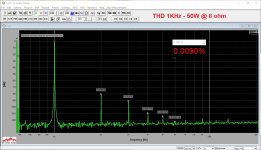
The second one's distortion level is definitely higher.
You will not see any difference on the scope. Nothing at all.
Attachments
Last edited:
Well, this is also not that easy 😉
Oscilloscope is not that precise, you will not see some 2-nd + 3rd harmonics at the level of 1% THD on the scope sine curve, however you will hear it. But you will definitely see those components on the spectrums. That's why we use spectrum analyzers for measuring distortion and clear understanding of its profile.
For example, here are two spectrums, measured on the real amplifiers.
The first one is a top-class amp, utilizing a non-switching output stage.
The second one's distortion level is definitely higher.
You will not see any difference on the scope. Nothing at all.
Absolutely. An FFT must be used. However, it also doesn't tell the full story. Crossover distortion sounds a lot worse than a little 3rd harmonic caused by device non-linearities. 1% distortion caused by crossover distortion (which is like a sore thumb) is far worse than 1% distortion due to device non-linearities (which are not easy to hear).
ETA: Now I sound like a "snake-oil" guy. The reason for the above is the myriad of frequency components added by crossover distortion.
Last edited:
Absolutely. An FFT must be used. However, it also doesn't tell the full story. Crossover distortion sounds a lot worse than a little 3rd harmonic caused by device non-linearities. 1% distortion caused by crossover distortion (which is like a sore thumb) is far worse than 1% distortion due to device non-linearities (which are not easy to hear).
ETA: Now I sound like a "snake-oil" guy. The reason for the above is the myriad of frequency components added by crossover distortion.
Yes, sure - crossover is a very bad one, producing lots of components.
The one I showed on the right is a properly biased class AB, so ... certain visible distortion is there, but it's got a good profile and no crossover dominance.
It is not your experience which we question, but your understanding. Experience does not always lead to understanding. We never claimed to know everything.LiquidMids said:I am an experienced tech, and you guys don't know everything.
No. There may be some people who could be confused by your 'explanation'.There are lots of people on here that can be helped by this explanation.
You seem to have invented some mental models (stories) to help yourself get your head around learning basic electronics, but then you made the classic newbie mistake of thinking that your stories are more true and more real than what you read in the textbooks. Hopefully you will eventually gain some real understanding. Humility will help.
I disagree. Pull thy ell halfway towards thyself and build up moderate tension by contering it with the other arm. Now either lower tension by releasing the ell or enlarge it by pulling the ell closer towards thy breast. Both acts work equally well, do they not?Like a muscle can only pull one way, so can a device. It can release, but not with the dynamic control it has contracting.
- Status
- Not open for further replies.
- Home
- Amplifiers
- Solid State
- Explanation of Class A